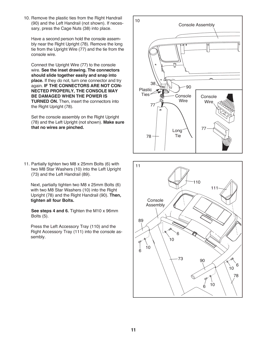
10. Remove the plastic ties from the Right Handrail | 10 |
|
|
|
|
|
|
|
(90) and the Left Handrail (not shown). If neces- |
|
| Console Assembly |
|
| |||
sary, press the Cage Nuts (38) into place. |
|
|
|
|
| |||
Have a second person hold the console assem- |
|
|
|
|
|
|
|
|
bly near the Right Upright (78). Remove the long |
|
|
|
|
|
|
|
|
tie from the Upright Wire (77) and the tie from the |
|
|
|
|
|
|
|
|
console wire. |
|
|
|
|
|
|
|
|
Connect the Upright Wire (77) to the console |
|
|
|
|
|
|
|
|
wire. See the inset drawing. The connectors |
|
|
|
|
|
|
|
|
should slide together easily and snap into |
|
|
|
|
|
|
|
|
place. If they do not, turn one connector and try |
| 38 |
|
|
|
|
|
|
again. IF THE CONNECTORS ARE NOT CON- |
|
| 90 |
|
|
|
| |
NECTED PROPERLY, THE CONSOLE MAY | Plastic |
| Console |
|
| |||
BE DAMAGED WHEN THE POWER IS |
| Ties |
| Console |
|
| ||
TURNED ON. Then, insert the connectors into |
| 77 |
| Wire | Wire |
|
| |
the Right Upright (78). |
|
|
|
|
| |||
Set the console assembly on the Right Upright |
|
|
|
|
|
|
|
|
(78) and the Left Upright (not shown). Make sure |
|
| Long | 77 |
|
|
| |
that no wires are pinched. |
| 78 |
|
|
| |||
|
|
| Tie |
|
|
|
| |
11. Partially tighten two M8 x 25mm Bolts (6) with | 11 |
|
|
|
|
|
|
|
two M8 Star Washers (10) into the Left Upright |
|
|
|
|
|
|
| |
(73) and the Left Handrail (89). |
|
|
|
| 110 |
|
|
|
Next, partially tighten two M8 x 25mm Bolts (6) |
|
|
|
| 111 |
|
| |
with two M8 Star Washers (10) into the Right |
|
|
|
|
|
|
| |
Upright (78) and the Right Handrail (90). Then, |
| Console |
|
|
|
|
|
|
tighten all four Bolts. |
|
|
|
|
|
|
| |
See steps 4 and 6. Tighten the M10 x 96mm |
| Assembly |
|
|
|
|
|
|
Bolts (5). | 89 |
|
|
|
|
|
| |
Press the Left Accessory Tray (110) and the |
|
|
|
|
|
| ||
Right Accessory Tray (111) into the console as- |
|
| 10 | 6 |
|
|
|
|
sembly. | 6 | 10 |
|
|
|
| ||
|
| 73 | 90 |
|
|
| ||
|
|
|
|
| 10 | 6 | ||
|
|
|
|
|
|
| ||
|
|
|
|
| 6 | 10 | 78 | |
|
|
|
|
|
|
| ||
| 11 |
|
|
|
|
|
|
|