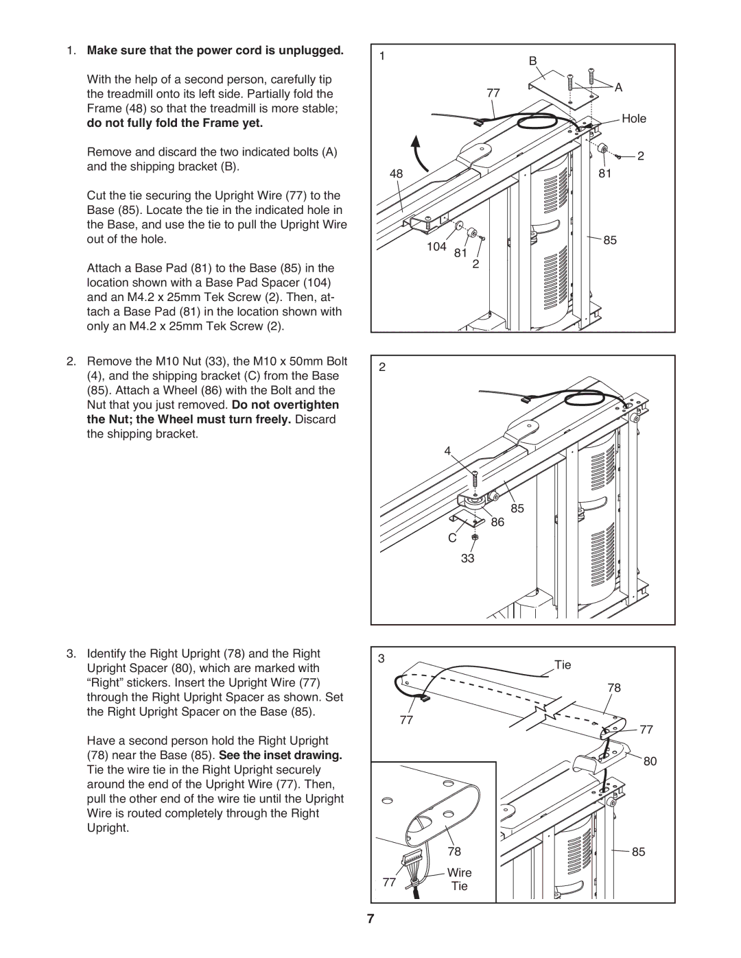
1. Make sure that the power cord is unplugged. | 1 |
|
|
| B |
|
|
With the help of a second person, carefully tip |
|
|
| 77 |
| A | |
the treadmill onto its left side. Partially fold the |
|
|
|
| |||
Frame (48) so that the treadmill is more stable; |
|
|
|
|
|
| Hole |
do not fully fold the Frame yet. |
|
|
|
|
|
| |
Remove and discard the two indicated bolts (A) | 48 |
|
|
|
| 81 | 2 |
and the shipping bracket (B). |
|
|
|
|
| ||
Cut the tie securing the Upright Wire (77) to the |
|
|
|
|
|
|
|
Base (85). Locate the tie in the indicated hole in |
|
|
|
|
|
|
|
the Base, and use the tie to pull the Upright Wire | 104 | 81 |
|
| 85 |
| |
out of the hole. | 2 |
|
| ||||
Attach a Base Pad (81) to the Base (85) in the |
|
|
|
|
|
| |
location shown with a Base Pad Spacer (104) |
|
|
|
|
|
|
|
and an M4.2 x 25mm Tek Screw (2). Then, at- |
|
|
|
|
|
|
|
tach a Base Pad (81) in the location shown with |
|
|
|
|
|
|
|
only an M4.2 x 25mm Tek Screw (2). |
|
|
|
|
|
|
|
2. Remove the M10 Nut (33), the M10 x 50mm Bolt | 2 |
|
|
|
|
|
|
(4), and the shipping bracket (C) from the Base |
|
|
|
|
|
| |
(85). Attach a Wheel (86) with the Bolt and the |
|
|
|
|
|
|
|
Nut that you just removed. Do not overtighten |
|
|
|
|
|
|
|
the Nut; the Wheel must turn freely. Discard |
|
|
|
|
|
|
|
the shipping bracket. | 4 |
|
|
|
|
| |
|
|
|
|
|
| ||
|
| C |
| 86 85 |
|
|
|
|
| 33 |
|
|
| ||
3. Identify the Right Upright (78) and the Right | 3 |
|
|
| Tie |
|
|
Upright Spacer (80), which are marked with |
|
|
|
|
| ||
“Right” stickers. Insert the Upright Wire (77) |
|
|
|
|
| 78 |
|
through the Right Upright Spacer as shown. Set |
|
|
|
|
|
| |
the Right Upright Spacer on the Base (85). | 77 |
|
|
|
|
| 77 |
Have a second person hold the Right Upright |
|
|
|
|
| ||
(78) near the Base (85). See the inset drawing. |
|
|
|
|
|
| 80 |
Tie the wire tie in the Right Upright securely |
|
|
|
|
|
| |
around the end of the Upright Wire (77). Then, |
|
|
|
|
|
|
|
pull the other end of the wire tie until the Upright |
|
|
|
|
|
|
|
Wire is routed completely through the Right |
|
|
|
|
|
|
|
Upright. |
| 78 |
|
|
|
| 85 |
| 77 | Wire |
|
|
|
| |
| Tie |
|
|
|
| ||
| 7 |
|
|
|
|
|
|