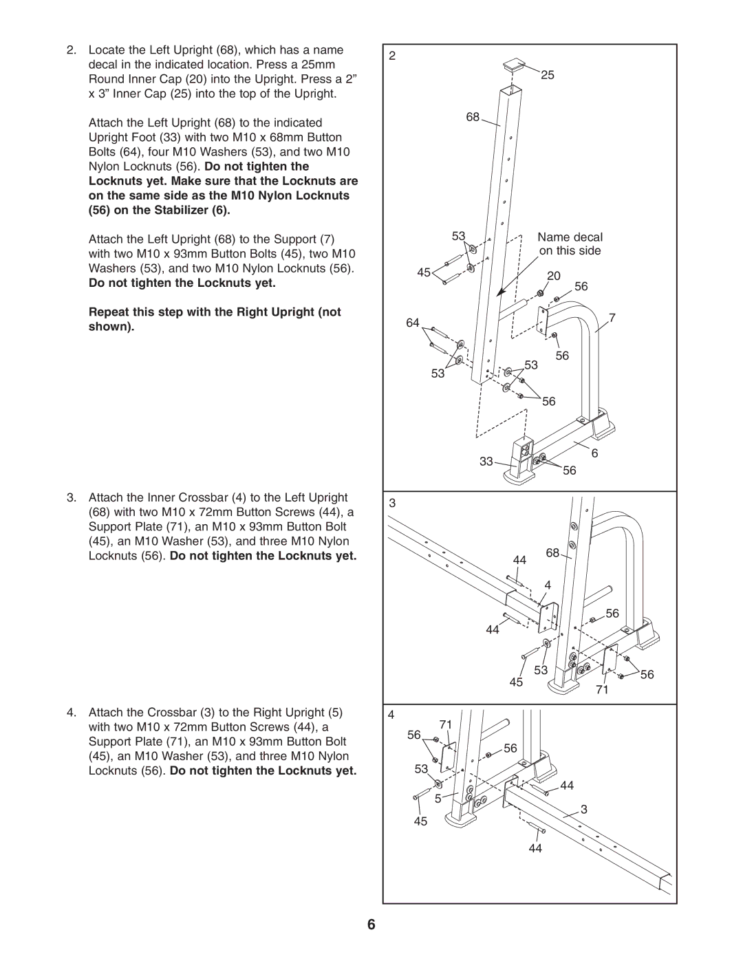
2.Locate the Left Upright (68), which has a name decal in the indicated location. Press a 25mm Round Inner Cap (20) into the Upright. Press a 2” x 3” Inner Cap (25) into the top of the Upright.
Attach the Left Upright (68) to the indicated Upright Foot (33) with two M10 x 68mm Button Bolts (64), four M10 Washers (53), and two M10 Nylon Locknuts (56). Do not tighten the
Locknuts yet. Make sure that the Locknuts are on the same side as the M10 Nylon Locknuts (56) on the Stabilizer (6).
Attach the Left Upright (68) to the Support (7) with two M10 x 93mm Button Bolts (45), two M10 Washers (53), and two M10 Nylon Locknuts (56).
Do not tighten the Locknuts yet.
Repeat this step with the Right Upright (not shown).
3.Attach the Inner Crossbar (4) to the Left Upright (68) with two M10 x 72mm Button Screws (44), a Support Plate (71), an M10 x 93mm Button Bolt (45), an M10 Washer (53), and three M10 Nylon Locknuts (56). Do not tighten the Locknuts yet.
4.Attach the Crossbar (3) to the Right Upright (5) with two M10 x 72mm Button Screws (44), a Support Plate (71), an M10 x 93mm Button Bolt (45), an M10 Washer (53), and three M10 Nylon Locknuts (56). Do not tighten the Locknuts yet.
2 |
|
|
|
|
|
|
| 25 |
|
| 68 |
|
|
|
53 |
|
| Name decal |
|
|
|
| on this side |
|
45 |
|
| 20 |
|
|
|
| 56 |
|
64 |
|
| 7 |
|
|
|
|
| |
|
|
| 56 |
|
53 |
| 53 |
| |
|
|
|
| |
|
|
| 56 |
|
| 33 |
| 6 |
|
|
| 56 |
| |
|
|
|
| |
3 |
|
|
|
|
| 44 | 68 |
| |
|
|
| ||
|
|
| 4 |
|
|
|
| 56 |
|
| 44 |
|
|
|
| 45 |
| 53 | 56 |
|
|
| ||
|
| 71 |
| |
|
|
|
| |
4 |
|
|
|
|
71 |
|
|
|
|
56 | 56 |
|
|
|
|
|
|
| |
53 |
|
|
|
|
5 |
|
| 44 |
|
|
| 3 |
| |
45 |
|
|
| |
|
|
|
| |
|
|
| 44 |
|
6