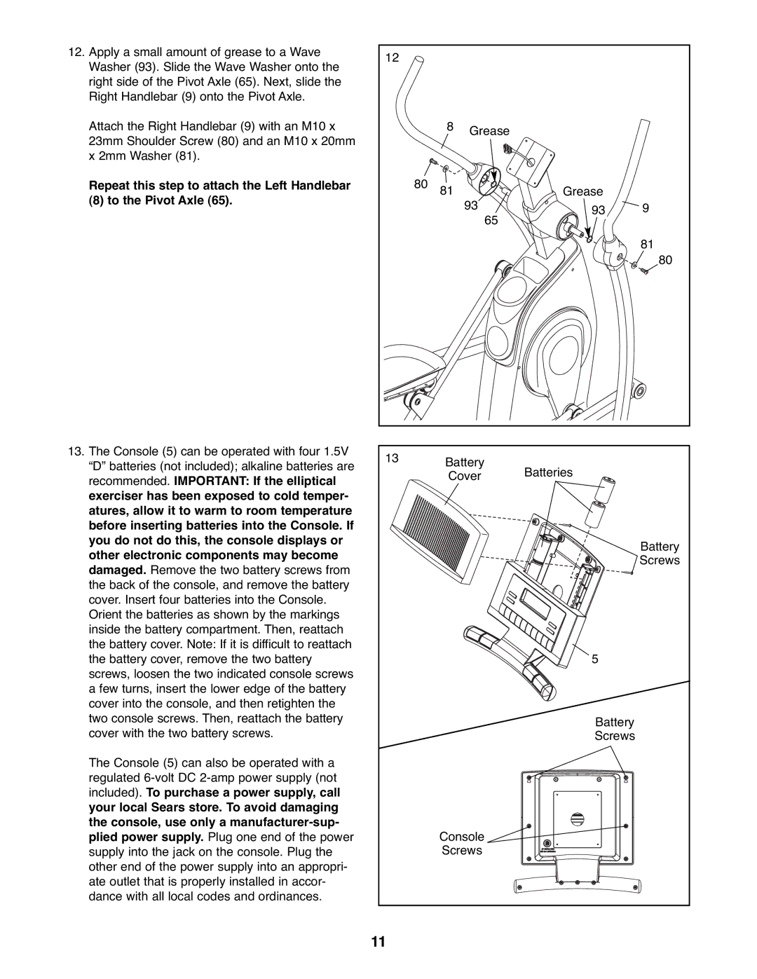
12.Apply a small amount of grease to a Wave Washer (93). Slide the Wave Washer onto the right side of the Pivot Axle (65). Next, slide the Right Handlebar (9) onto the Pivot Axle.
Attach the Right Handlebar (9) with an M10 x 23mm Shoulder Screw (80) and an M10 x 20mm x 2mm Washer (81).
Repeat this step to attach the Left Handlebar
(8) to the Pivot Axle (65).
12 |
|
|
|
|
| 8 | Grease |
|
|
80 | 81 | 93 | Grease |
|
|
| 93 | 9 | |
|
| 65 |
|
|
|
|
|
| 81 |
|
|
|
| 80 |
13. The Console (5) can be operated with four 1.5V | 13 | Battery |
|
“D” batteries (not included); alkaline batteries are |
| ||
| Batteries | ||
| Cover | ||
recommended. IMPORTANT: If the elliptical |
| ||
|
|
| |
exerciser has been exposed to cold temper- |
|
|
|
atures, allow it to warm to room temperature |
|
|
|
before inserting batteries into the Console. If |
|
|
|
you do not do this, the console displays or |
|
| Battery |
other electronic components may become |
|
| |
|
| Screws | |
damaged. Remove the two battery screws from |
|
| |
|
|
| |
the back of the console, and remove the battery |
|
|
|
cover. Insert four batteries into the Console. |
|
|
|
Orient the batteries as shown by the markings |
|
|
|
inside the battery compartment. Then, reattach |
|
|
|
the battery cover. Note: If it is difficult to reattach |
|
|
|
the battery cover, remove the two battery |
|
| 5 |
screws, loosen the two indicated console screws |
|
|
|
a few turns, insert the lower edge of the battery |
|
|
|
cover into the console, and then retighten the |
|
|
|
two console screws. Then, reattach the battery |
|
| Battery |
cover with the two battery screws. |
|
| |
|
| Screws | |
The Console (5) can also be operated with a |
|
|
|
regulated |
|
|
|
included). To purchase a power supply, call |
|
|
|
your local Sears store. To avoid damaging |
|
|
|
the console, use only a |
|
|
|
plied power supply. Plug one end of the power |
| Console |
|
supply into the jack on the console. Plug the |
| Screws |
|
other end of the power supply into an appropri- |
|
|
|
ate outlet that is properly installed in accor- |
|
|
|
dance with all local codes and ordinances. |
|
|
|
| 11 |
|
|