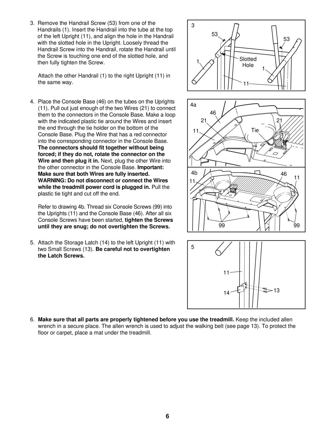
3.Remove the Handrail Screw (53) from one of the
Handrails (1). Insert the Handrail into the tube at the top
of the left Upright (11), and align the hole in the Handrail with the slotted hole in the Upright. Loosely thread the Handrail Screw into the Handrail, rotate the Handrail until
the Screw is touching one end of the slotted hole, and then fully tighten the Screw.
Attach the other Handrail (1) to the right Upright (11) in the same way.
4.Place the Console Base (46) on the tubes on the Uprights
(11). Pull out just enough of the two Wires (21) to connect them to the connectors in the Console Base. Make a loop
with the indicated plastic tie around the Wires and insert the end through the tie holder on the bottom of the Console Base. Plug the Wire that has a red connector
into the corresponding connector in the Console Base.
The connectors should fit together without being forced; if they do not, rotate the connector on the
Wire and then plug it in. | Next, plug the other Wire into | |
the other connector in the Console Base. | Important: | |
Make sure that both Wires are fully inserted. |
| |
WARNING: Do not disconnect or connect the Wires |
| |
while the treadmill power cord is plugged in. | Pull the | |
plastic tie tight and cut off the end. |
| |
Refer to drawing 4b. Thread six Console Screws (99) into
the Uprights (11) and the Console Base (46). After all six
Console Screws have been started, tighten the Screws
until they are snug; do not overtighten the Screws.
5. Attach the Storage Latch (14) to the left Upright (11) with
two Small Screws (13). Be careful not to overtighten the Latch Screws.
3 |
|
|
| 53 | 53 |
|
| |
1 | Slotted |
|
Hole |
| |
| 1 | |
|
| |
| 11 |
|
4a |
|
|
| 46 |
|
21 |
| 21 |
11 | Tie |
|
4b | 46 |
11 | 11 |
|
99 | 99 |
5
11![]()
14 ![]()
![]()
![]() 13
13
6. Make sure that all parts are properly tightened before you use the treadmill.Keep the included allen
wrench in a secure place. The allen wrench is used to adjust the walking belt (see page 13). To protect the floor or carpet, place a mat under the treadmill.
6