multiPort Configured as a Parallel Port
The parallel port is available on connector CN6. Make sure the multiPort in the BIOS Setup is configured to parallel port. You can use the BIOS Setup to select the parallel port’s address and associated interrupt, and choose between its operational modes (SPP, ECP, EPP 1.7, and EPP 1.9).
The pinout of the connector enables a ribbon cable to be connected directly to a
Note For correct operation, keep the length of the cable connecting the cpuModule and parallel device less than 3 meters (10 feet).
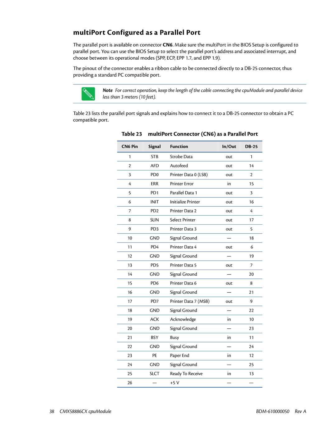
Table 23 lists the parallel port signals and explains how to connect it to a
Table 23 multiPort Connector (CN6) as a Parallel Port
CN6 Pin | Signal | Function | In/Out |
|
|
|
|
|
|
1 | STB | Strobe Data | out | 1 |
|
|
|
|
|
2 | AFD | Autofeed | out | 14 |
|
|
|
|
|
3 | PD0 | Printer Data 0 (LSB) | out | 2 |
|
|
|
|
|
4 | ERR | Printer Error | in | 15 |
|
|
|
|
|
5 | PD1 | Parallel Data 1 | out | 3 |
|
|
|
|
|
6 | INIT | Initialize Printer | out | 16 |
|
|
|
|
|
7 | PD2 | Printer Data 2 | out | 4 |
|
|
|
|
|
8 | SLIN | Select Printer | out | 17 |
|
|
|
|
|
9 | PD3 | Printer Data 3 | out | 5 |
|
|
|
|
|
10 | GND | Signal Ground | — | 18 |
|
|
|
|
|
11 | PD4 | Printer Data 4 | out | 6 |
|
|
|
|
|
12 | GND | Signal Ground | — | 19 |
|
|
|
|
|
13 | PD5 | Printer Data 5 | out | 7 |
|
|
|
|
|
14 | GND | Signal Ground | — | 20 |
|
|
|
|
|
15 | PD6 | Printer Data 6 | out | 8 |
|
|
|
|
|
16 | GND | Signal Ground | — | 21 |
|
|
|
|
|
17 | PD7 | Printer Data 7 (MSB) | out | 9 |
|
|
|
|
|
18 | GND | Signal Ground | — | 22 |
|
|
|
|
|
19 | ACK | Acknowledge | in | 10 |
|
|
|
|
|
20 | GND | Signal Ground | — | 23 |
|
|
|
|
|
21 | BSY | Busy | in | 11 |
|
|
|
|
|
22 | GND | Signal Ground | — | 24 |
|
|
|
|
|
23 | PE | Paper End | in | 12 |
|
|
|
|
|
24 | GND | Signal Ground | — | 25 |
|
|
|
|
|
25 | SLCT | Ready To Receive | in | 13 |
|
|
|
|
|
26 | — | +5 V | — | — |
|
|
|
|
|
38 CMX58886CX cpuModule |