ATA/IDE Disk Chip Socket (U16)
The ATA/IDE Disk Chip socket is a
WARNING Before installing a device in the ATA/IDE Disk Chip socket, the system must be configured in the correct mode. For details on configuring the socket, refer to Chapter 4, Using the cpuModule.
WARNING The ATA/IDE Disk Chip socket does not support conventional SSD memory devices or devices that install as a BIOS extension (such as the
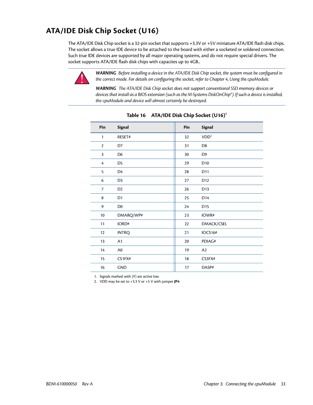
Table 16 ATA/IDE Disk Chip Socket (U16)1
Pin | Signal |
| Pin | Signal |
|
|
|
|
|
1 | RESET# |
| 32 | VDD2 |
|
|
|
|
|
2 | D7 |
| 31 | D8 |
|
|
|
|
|
3 | D6 |
| 30 | D9 |
|
|
|
|
|
4 | D5 |
| 29 | D10 |
|
|
|
|
|
5 | D4 |
| 28 | D11 |
|
|
|
|
|
6 | D3 |
| 27 | D12 |
|
|
|
|
|
7 | D2 |
| 26 | D13 |
|
|
|
|
|
8 | D1 |
| 25 | D14 |
|
|
|
|
|
9 | D0 |
| 24 | D15 |
|
|
|
|
|
10 | DMARQ/WP# |
| 23 | IOWR# |
|
|
|
|
|
11 | IORD# |
| 22 | DMACK/CSEL |
|
|
|
|
|
12 | INTRQ |
| 21 | IOCS16# |
|
|
|
|
|
13 | A1 |
| 20 | PDIAG# |
|
|
|
|
|
14 | A0 |
| 19 | A2 |
|
|
|
|
|
15 | CS1FX# |
| 18 | CS3FX# |
|
|
|
|
|
16 | GND |
| 17 | DASP# |
|
|
|
|
|
1.Signals marked with (#) are active low.
2.VDD may be set to +3.3 V or +5 V with jumper JP4
Chapter 3: Connecting the cpuModule 33 |