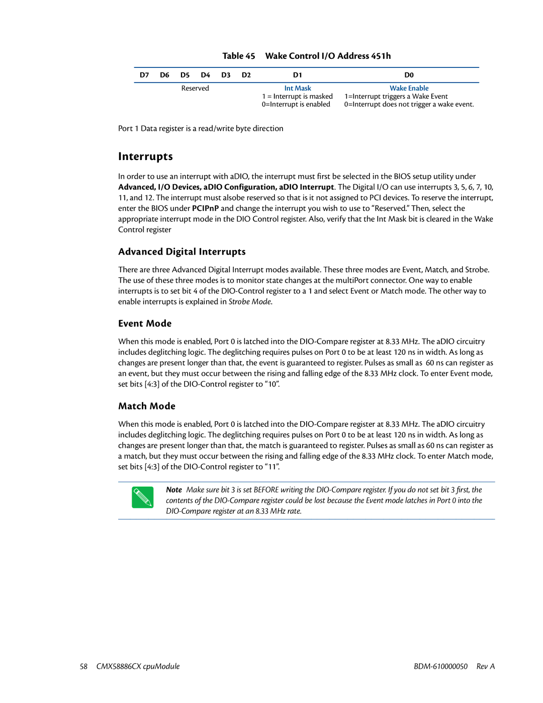
Table 45 Wake Control I/O Address 451h
D7 | D6 | D5 | D4 | D3 | D2 | D1 | D0 |
|
| Reserved |
|
| Int Mask | Wake Enable | |
|
|
|
|
|
| 1 = Interrupt is masked | 1=Interrupt triggers a Wake Event |
|
|
|
|
|
| 0=Interrupt is enabled | 0=Interrupt does not trigger a wake event. |
Port 1 Data register is a read/write byte direction
Interrupts
In order to use an interrupt with aDIO, the interrupt must first be selected in the BIOS setup utility under Advanced, I/O Devices, aDIO Configuration, aDIO Interrupt. The Digital I/O can use interrupts 3, 5, 6, 7, 10, 11, and 12. The interrupt must alsobe reserved so that is it not assigned to PCI devices. To reserve the interrupt, enter the BIOS under PCIPnP and change the interrupt you wish to use to “Reserved.” Then, select the appropriate interrupt mode in the DIO Control register. Also, verify that the Int Mask bit is cleared in the Wake Control register
Advanced Digital Interrupts
There are three Advanced Digital Interrupt modes available. These three modes are Event, Match, and Strobe. The use of these three modes is to monitor state changes at the multiPort connector. One way to enable interrupts is to set bit 4 of the
Event Mode
When this mode is enabled, Port 0 is latched into the
Match Mode
When this mode is enabled, Port 0 is latched into the
Note Make sure bit 3 is set BEFORE writing the
58 CMX58886CX cpuModule |