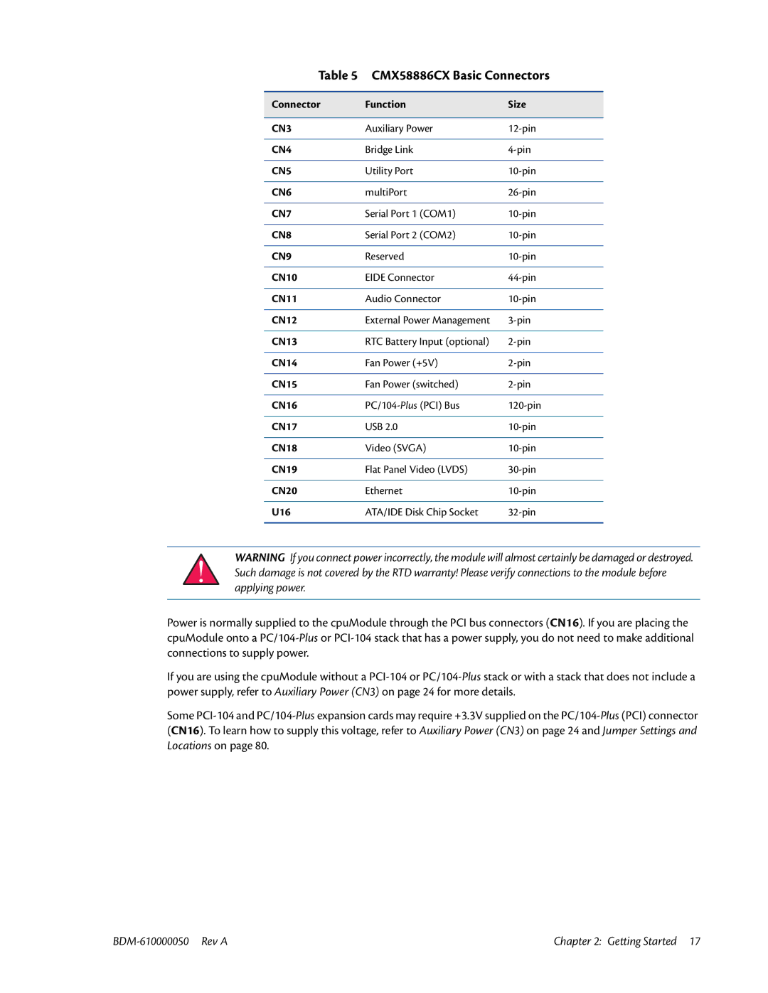
Table 5 CMX58886CX Basic Connectors
Connector | Function | Size |
|
|
|
CN3 | Auxiliary Power | |
|
|
|
CN4 | Bridge Link | |
|
|
|
CN5 | Utility Port | |
|
|
|
CN6 | multiPort | |
|
|
|
CN7 | Serial Port 1 (COM1) | |
|
|
|
CN8 | Serial Port 2 (COM2) | |
|
|
|
CN9 | Reserved | |
|
|
|
CN10 | EIDE Connector | |
|
|
|
CN11 | Audio Connector | |
|
|
|
CN12 | External Power Management | |
|
|
|
CN13 | RTC Battery Input (optional) | |
|
|
|
CN14 | Fan Power (+5V) | |
|
|
|
CN15 | Fan Power (switched) | |
|
|
|
CN16 | ||
|
|
|
CN17 | USB 2.0 | |
|
|
|
CN18 | Video (SVGA) | |
|
|
|
CN19 | Flat Panel Video (LVDS) | |
|
|
|
CN20 | Ethernet | |
|
|
|
U16 | ATA/IDE Disk Chip Socket | |
|
|
|
WARNING If you connect power incorrectly, the module will almost certainly be damaged or destroyed. Such damage is not covered by the RTD warranty! Please verify connections to the module before applying power.
Power is normally supplied to the cpuModule through the PCI bus connectors (CN16). If you are placing the cpuModule onto a
If you are using the cpuModule without a
Some
Chapter 2: Getting Started 17 |