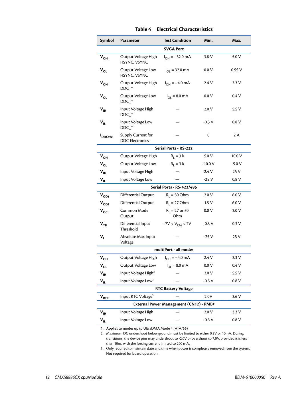
Table 4 Electrical Characteristics
Symbol | Parameter | Test Condition | Min. | Max. |
|
|
|
|
|
|
| SVGA Port |
|
|
|
|
|
|
|
VOH | Output Voltage High | IOH = | 3.8 V | 5.0 V |
| HSYNC, VSYNC |
|
|
|
VOL | Output Voltage Low | IOL = 32.0 mA | 0.0 V | 0.55 V |
| HSYNC, VSYNC |
|
|
|
VOH | Output Voltage High | IOH = | 2.4 V | 3.3 V |
| DDC_* |
|
|
|
VOL | Output Voltage Low | IOL = 8.0 mA | 0.0 V | 0.4 V |
| DDC_* |
|
|
|
VIH | Input Voltage High | — | 2.0 V | 5.5 V |
| DDC_* |
|
|
|
VIL | Input Voltage Low | — | 0.8 V | |
| DDC_* |
|
|
|
IDDCvcc | Supply Current for | — | 0 | 2 A |
| DDC Electronics |
|
|
|
|
|
|
| |
| Serial Ports - |
|
| |
|
|
|
|
|
VOH | Output Voltage High | RL = 3 k | 5.0 V | 10.0 V |
VOL | Output Voltage Low | RL = 3 k | ||
VIH | Input Voltage High | — | 2.4 V | 25 V |
VIL | Input Voltage Low | — | 0.8 V | |
| Serial Ports - |
|
| |
|
|
|
|
|
VOD1 | Differential Output | RL = 50 Ohm | 2.0 V | 6.0 V |
VOD2 | Differential Output | RL = 27 Ohm | 1.5 V | 6.0 V |
VOC | Common Mode | RL = 27 or 50 | 0.0 V | 3.0 V |
| Output | Ohm |
|
|
VTH | Differential Input | 0.3 V | ||
| Threshold |
|
|
|
VI | Absolute Max Input | — | 25 V | |
| Voltage |
|
|
|
|
|
|
| |
| multiPort - all modes |
|
| |
|
|
|
|
|
VOH | Output Voltage High | IOH = | 2.4 V | 3.3 V |
VOL | Output Voltage Low | IOL = 8.0 mA | 0.0 V | 0.4 V |
V | Input Voltage High2 | — | 2.0 V | 5.5 V |
IH |
|
|
|
|
V | Input Voltage Low2 | — | 0.8 V | |
IL |
|
|
|
|
| RTC Battery Voltage |
|
| |
|
|
|
|
|
VRTC | Input RTC Voltage3 | — | 2.0V | 3.6 V |
| External Power Management (CN12) - PME# |
| ||
|
|
|
|
|
VIH | Input Voltage High | — | 2.0 V | 3.3 V |
VIL | Input Voltage Low | — | 0.8 V | |
1.Applies to modes up to UltraDMA Mode 4 (ATA/66)
2.Maximum DC undershoot below ground must be limited to either 0.5V or 10mA. During transitions, the device pins may undershoot to
3.Only required to maintain date and time when power is completely removed from the system. Not required for board operation.
12 CMX58886CX cpuModule |