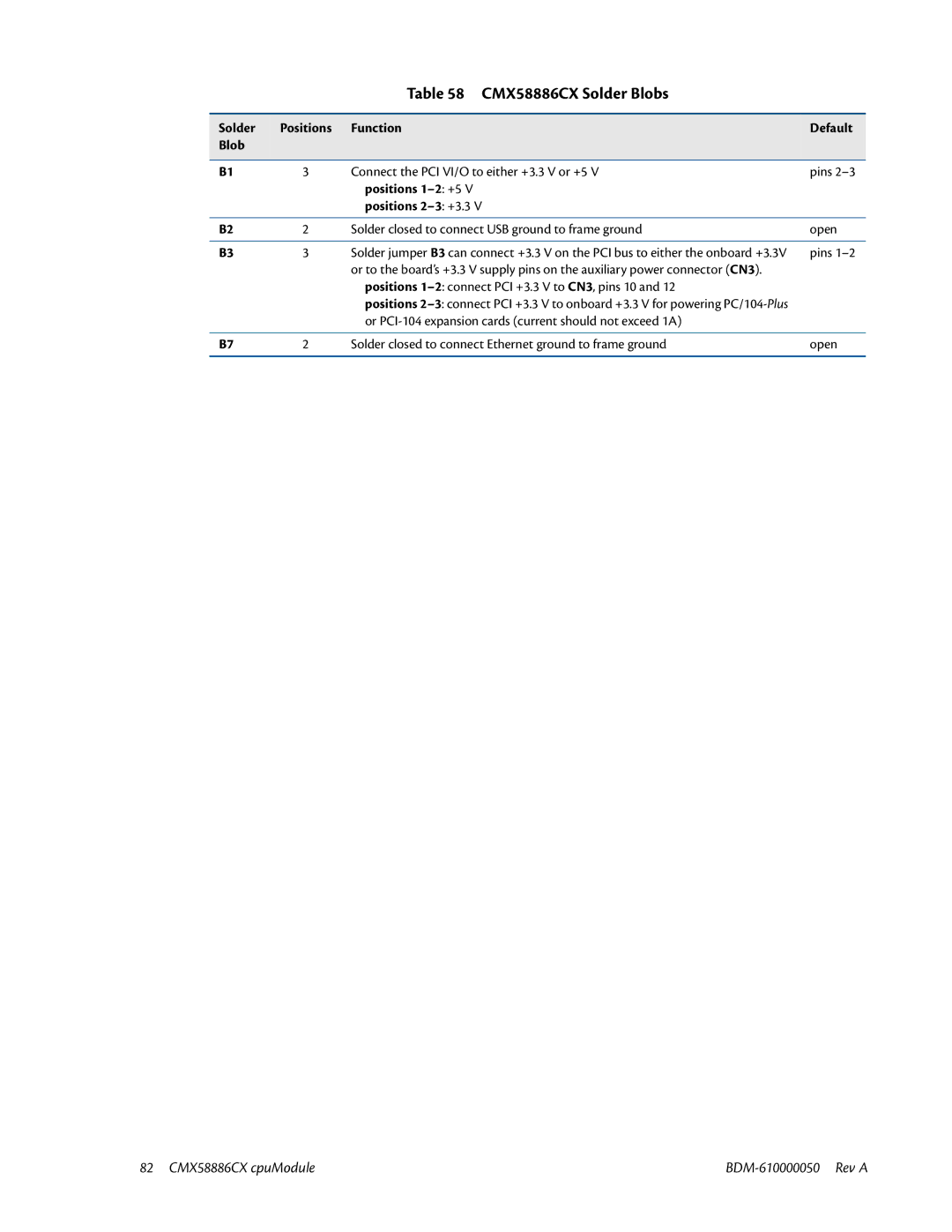
Table 58 CMX58886CX Solder Blobs
Solder | Positions | Function | Default |
Blob |
|
|
|
|
|
|
|
B1 | 3 | Connect the PCI VI/O to either +3.3 V or +5 V | pins |
|
| positions |
|
|
| positions |
|
|
|
|
|
B2 | 2 | Solder closed to connect USB ground to frame ground | open |
|
|
|
|
B3 | 3 | Solder jumper B3 can connect +3.3 V on the PCI bus to either the onboard +3.3V | pins |
|
| or to the board’s +3.3 V supply pins on the auxiliary power connector (CN3). |
|
|
| positions |
|
|
| positions |
|
|
| or |
|
|
|
|
|
B7 | 2 | Solder closed to connect Ethernet ground to frame ground | open |
|
|
|
|
82 CMX58886CX cpuModule |