ASSEMBLY
Assembly requires two people. | Set the treadmill in a cleared area and remove all packing materials. Do not | ||
dispose of the packing materials | until assembly is completed. | Assembly requires your own phillips screw- | |
driver | and | rubber mallet | . |
Note: The underside of the treadmill walking belt is coated with
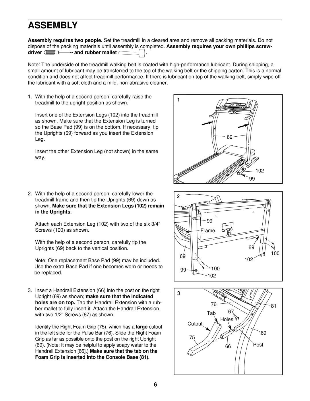
1. With the help of a second person, carefully raise the |
| 1 |
|
|
| ||||
| treadmill to the upright position as shown. |
|
|
|
| ||||
|
|
|
|
|
| ||||
| Insert one of the Extension Legs (102) into the treadmill |
|
|
|
| ||||
| as shown. Make sure that the Extension Leg is turned |
|
|
|
|
| |||
| so the Base Pad (99) is on the bottom. If necessary, tip |
|
|
|
|
| |||
| the Uprights (69) forward as you insert the Extension |
|
|
| 69 |
| |||
| Leg. |
|
|
|
|
|
|
| |
|
|
|
|
|
|
|
|
| |
| Insert the other Extension Leg (not shown) in the same |
|
|
|
|
| |||
| way. |
|
|
|
|
|
|
|
|
|
|
|
|
|
|
|
|
| 102 |
|
|
|
|
|
|
|
|
| 99 |
2. With the help of a second person, carefully lower the |
| 2 |
|
|
| ||||
| treadmill frame and then tip the Uprights (69) down as |
|
|
|
| ||||
|
|
|
|
|
| ||||
| shown. | Make sure that the Extension Legs (102) remain |
|
|
|
| |||
| in the Uprights. |
|
|
|
|
|
|
| |
| Attach each Extension Leg (102) with two of the six 3/4” |
| 99 |
|
| ||||
|
|
|
|
| |||||
| Screws (100) as shown. |
|
|
| Frame |
|
| ||
| With the help of a second person, carefully tip the |
|
|
|
| 69 | |||
| Uprights (69) back to the vertical position. |
|
|
|
| ||||
|
|
|
|
|
| 69 |
|
| 100 |
| Note: One replacement Base Pad (99) may be included. |
|
|
| 102 | ||||
|
|
|
|
| |||||
| Use the extra Base Pad if one becomes worn or needs to |
| 99 | 100 |
|
| |||
| be replaced. |
|
|
|
|
|
| ||
|
|
|
|
|
| 102 |
|
| |
|
|
|
|
|
|
|
|
| |
3. | Insert a Handrail Extension (66) into the | post on the right | 3 |
|
|
| |||
| Upright (69) as shown; | make sure that the indicated |
|
|
|
| |||
|
|
|
|
|
| ||||
| holes are on top. | Tap the Handrail Extension with a rub- |
| 76 |
| 81 | |||
| ber mallet to fully insert it. Attach the Handrail Extension |
|
|
| |||||
|
|
|
| 67 | |||||
|
|
| Tab |
| |||||
| with two 1/2” | Screws (67) as shown. |
|
|
| ||||
|
|
|
|
| |||||
|
|
|
| Holes |
| ||||
|
|
|
|
|
|
| Cutout |
| |
| Identify the Right Foam Grip (75), which has a | large | cutout |
|
| ||||
|
|
|
| ||||||
| in the left side for the Pulse Bar (76). Slide the Right Foam |
|
| 75 |
| 69 | |||
| Grip as far as possible onto the post on the right Upright |
|
|
|
| ||||
|
|
|
|
| Post | ||||
| (69). (Note: It may be helpful to apply soapy water to the |
|
| 66 | |||||
| Handrail Extension [66].) | Make sure that the tab on the |
|
|
|
| |||
| Foam Grip is inserted into the Console Base (81). |
|
|
|
|
| |||
|
|
|
|
|
| 6 |
|
|
|