PART IDENTIFICATION CHART
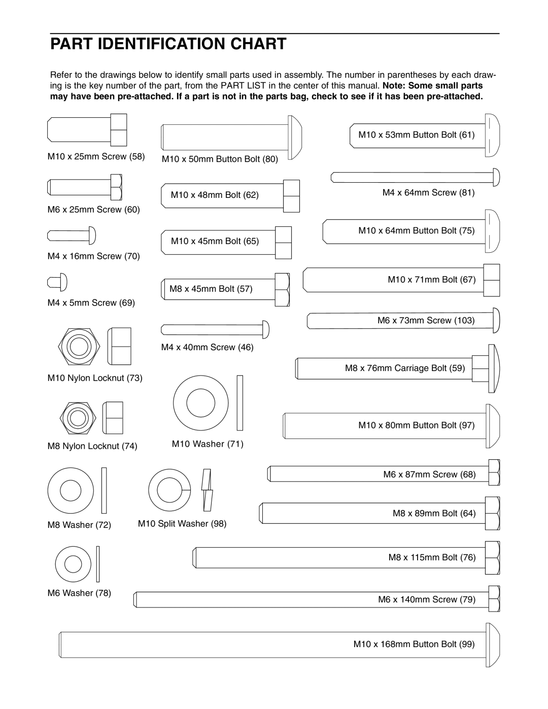
Refer to the drawings below to identify small parts used in assembly. The number in parentheses by each draw- ing is the key number of the part, from the PART LIST in the center of this manual. Note: Some small parts may have been
|
|
|
|
|
|
|
|
|
|
|
|
|
|
|
|
|
|
|
|
| M10 x 53mm Button Bolt (61) |
|
|
|
|
|
|
|
|
|
|
|
|
|
|
|
|
|
|
|
|
|
|
M10 x 25mm Screw (58) |
|
|
|
|
|
|
| |||
M10 x 50mm Button Bolt (80) |
|
|
|
|
| |||||
|
|
|
|
|
|
| ||||
M10 x 48mm Bolt (62) | M4 x 64mm Screw (81) |
M6 x 25mm Screw (60) |
|
| M10 x 64mm Button Bolt (75) |
M10 x 45mm Bolt (65) |
|
M4 x 16mm Screw (70) |
|
M8 x 45mm Bolt (57) | M10 x 71mm Bolt (67) |
| |
M4 x 5mm Screw (69) |
|
| M6 x 73mm Screw (103) |
M4 x 40mm Screw (46)
M8 x 76mm Carriage Bolt (59)
M10 Nylon Locknut (73)
M10 x 80mm Button Bolt (97)
M8 Nylon Locknut (74) | M10 Washer (71) |
M6 x 87mm Screw (68)
M8 x 89mm Bolt (64)
M8 Washer (72) | M10 Split Washer (98) |
M8 x 115mm Bolt (76)
M6 Washer (78)
M6 x 140mm Screw (79)
M10 x 168mm Button Bolt (99)