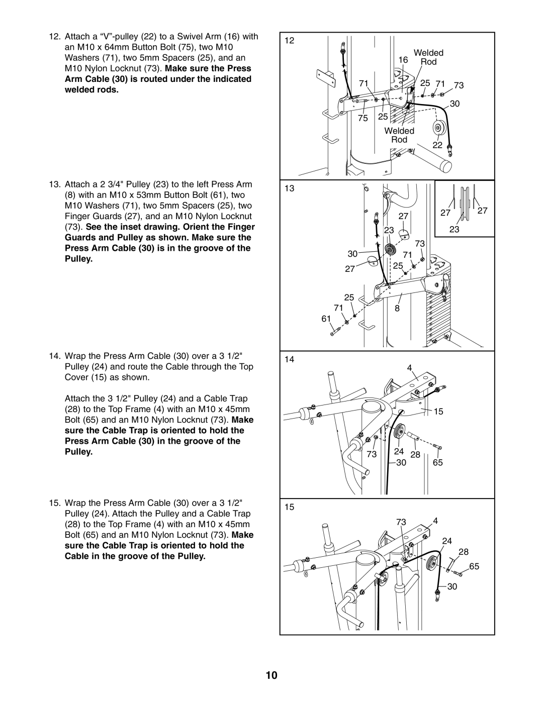
12.Attach a
Arm Cable (30) is routed under the indicated welded rods.
13.Attach a 2 3/4" Pulley (23) to the left Press Arm
(8)with an M10 x 53mm Button Bolt (61), two M10 Washers (71), two 5mm Spacers (25), two Finger Guards (27), and an M10 Nylon Locknut
(73).See the inset drawing. Orient the Finger Guards and Pulley as shown. Make sure the Press Arm Cable (30) is in the groove of the Pulley.
14.Wrap the Press Arm Cable (30) over a 3 1/2" Pulley (24) and route the Cable through the Top Cover (15) as shown.
Attach the 3 1/2" Pulley (24) and a Cable Trap
(28)to the Top Frame (4) with an M10 x 45mm Bolt (65) and an M10 Nylon Locknut (73). Make sure the Cable Trap is oriented to hold the Press Arm Cable (30) in the groove of the Pulley.
15.Wrap the Press Arm Cable (30) over a 3 1/2" Pulley (24). Attach the Pulley and a Cable Trap
(28)to the Top Frame (4) with an M10 x 45mm Bolt (65) and an M10 Nylon Locknut (73). Make sure the Cable Trap is oriented to hold the Cable in the groove of the Pulley.
12 |
|
|
|
|
| 16 | Welded |
| |
| Rod |
| ||
71 |
| 25 | 71 | 73 |
|
|
| 30 | |
75 | 25 |
|
|
|
| Welded |
|
| |
| Rod |
| 22 |
|
|
|
|
| |
13 |
|
|
|
|
| 27 |
| 27 | 27 |
|
|
|
| |
| 23 |
| 23 | |
30 |
| 73 |
|
|
71 |
|
| ||
27 | 25 |
|
|
|
|
|
|
| |
25 |
|
|
|
|
71 | 8 |
|
|
|
61 |
|
|
|
|
14 | 4 |
|
| |
|
|
| ||
|
|
| 15 |
|
73 | 24 | 28 | 65 |
|
| 30 |
|
| |
15 |
|
|
|
|
| 73 |
| 4 |
|
|
|
| 24 |
|
|
|
|
| 28 |
|
|
|
| 65 |
|
|
| 30 | |
10