ASSEMBLY
Assembly requires two persons. Set the treadmill in a cleared area and remove all packing materials; do not dispose of the packing materials until assembly is completed. Note: The underside of the treadmill walking belt is coated with
Assembly requires the included allen wrench | and your own phillips screwdriver | , | ||
adjustable wrench | , and rubber mallet | . |
| |
1.Note: Use the PART IDENTIFICATION CHART in the center of this manual to identify small parts used during assembly.
Do not plug in the power cord until all the assembly steps are completed.
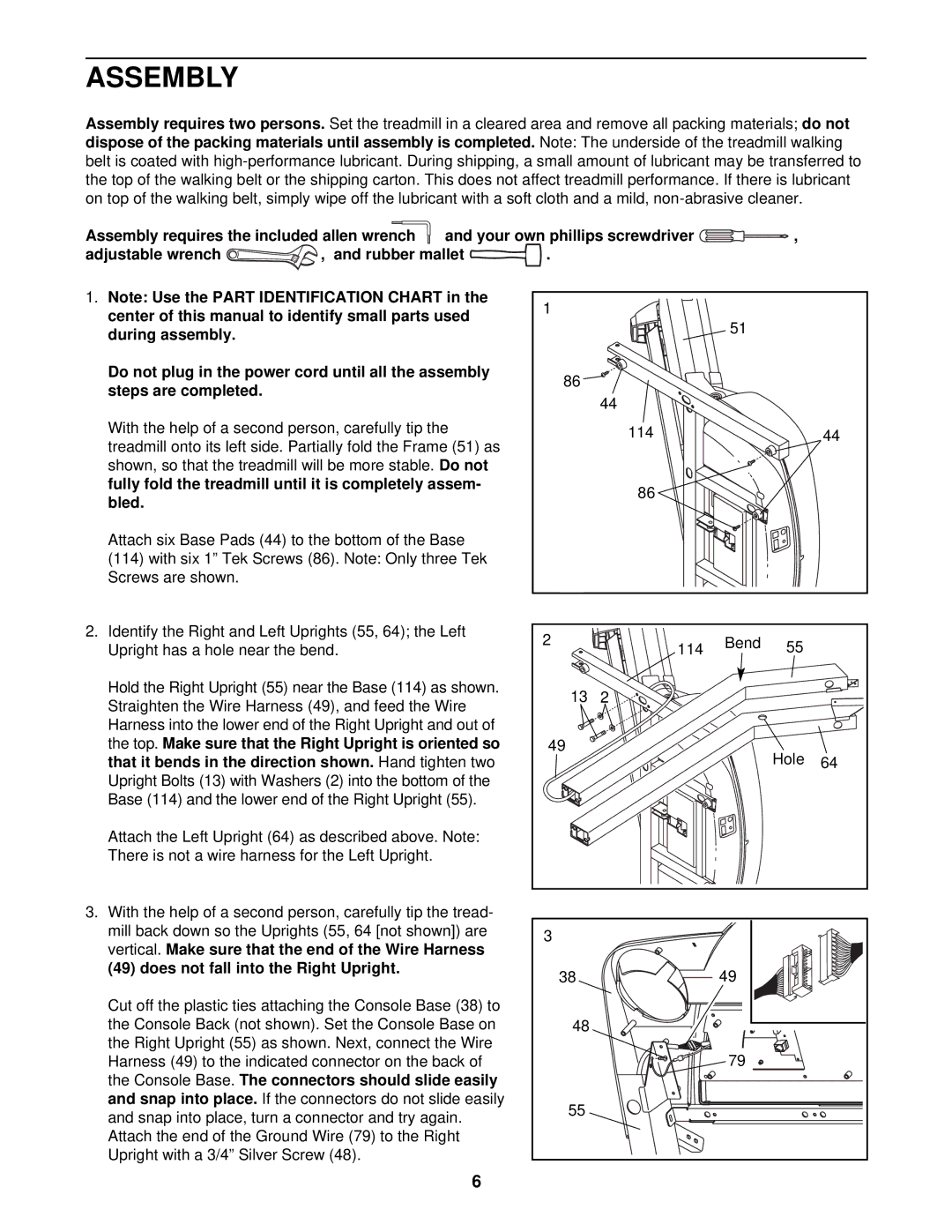
With the help of a second person, carefully tip the treadmill onto its left side. Partially fold the Frame (51) as shown, so that the treadmill will be more stable. Do not fully fold the treadmill until it is completely assem- bled.
Attach six Base Pads (44) to the bottom of the Base (114) with six 1” Tek Screws (86). Note: Only three Tek Screws are shown.
2.Identify the Right and Left Uprights (55, 64); the Left Upright has a hole near the bend.
Hold the Right Upright (55) near the Base (114) as shown. Straighten the Wire Harness (49), and feed the Wire Harness into the lower end of the Right Upright and out of the top. Make sure that the Right Upright is oriented so that it bends in the direction shown. Hand tighten two Upright Bolts (13) with Washers (2) into the bottom of the Base (114) and the lower end of the Right Upright (55).
Attach the Left Upright (64) as described above. Note: There is not a wire harness for the Left Upright.
1 |
|
|
|
|
|
| 51 |
|
|
86 |
|
|
|
|
| 44 |
|
|
|
| 114 |
|
| 44 |
| 86 |
|
|
|
2 | 114 | Bend | 55 |
|
|
| |||
13 | 2 |
|
|
|
49 |
|
| Hole | 64 |
|
|
|
3.With the help of a second person, carefully tip the tread- mill back down so the Uprights (55, 64 [not shown]) are vertical. Make sure that the end of the Wire Harness (49) does not fall into the Right Upright.
Cut off the plastic ties attaching the Console Base (38) to the Console Back (not shown). Set the Console Base on the Right Upright (55) as shown. Next, connect the Wire Harness (49) to the indicated connector on the back of the Console Base. The connectors should slide easily and snap into place. If the connectors do not slide easily and snap into place, turn a connector and try again. Attach the end of the Ground Wire (79) to the Right Upright with a 3/4” Silver Screw (48).
3 |
|
38 | 49 |
48 |
|
| 79 |
55 |
|
6