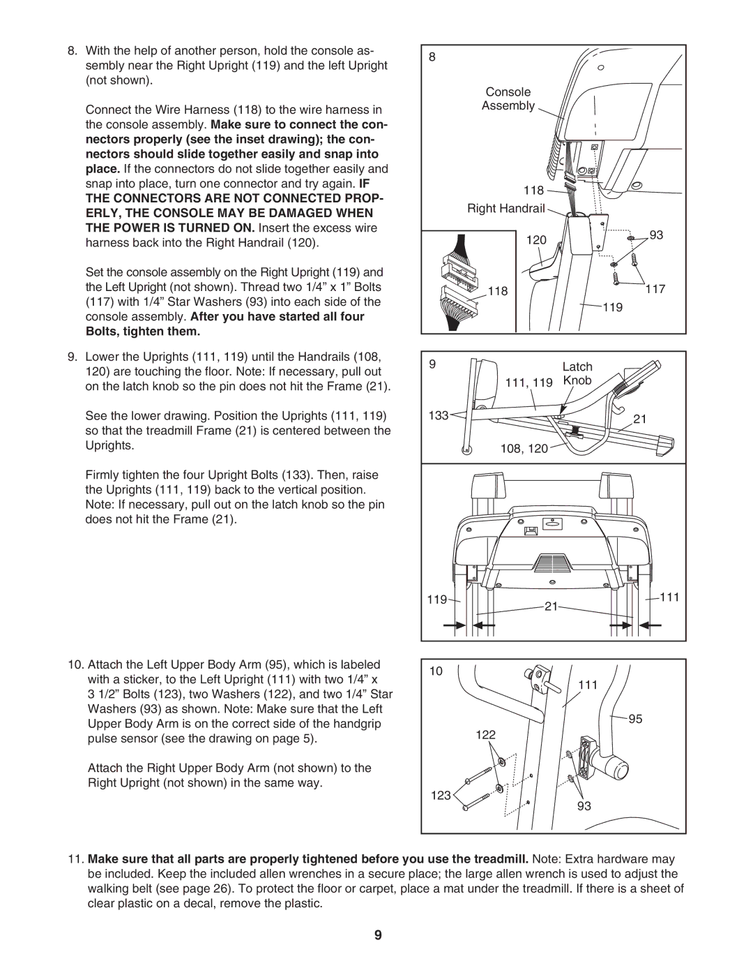
8.With the help of another person, hold the console as- sembly near the Right Upright (119) and the left Upright (not shown).
Connect the Wire Harness (118) to the wire harness in the console assembly. Make sure to connect the con- nectors properly (see the inset drawing); the con- nectors should slide together easily and snap into place. If the connectors do not slide together easily and snap into place, turn one connector and try again. IF
THE CONNECTORS ARE NOT CONNECTED PROP- ERLY, THE CONSOLE MAY BE DAMAGED WHEN THE POWER IS TURNED ON. Insert the excess wire harness back into the Right Handrail (120).
Set the console assembly on the Right Upright (119) and the Left Upright (not shown). Thread two 1/4” x 1” Bolts (117) with 1/4” Star Washers (93) into each side of the console assembly. After you have started all four
Bolts, tighten them.
9.Lower the Uprights (111, 119) until the Handrails (108, 120) are touching the floor. Note: If necessary, pull out on the latch knob so the pin does not hit the Frame (21).
See the lower drawing. Position the Uprights (111, 119) so that the treadmill Frame (21) is centered between the Uprights.
Firmly tighten the four Upright Bolts (133). Then, raise the Uprights (111, 119) back to the vertical position. Note: If necessary, pull out on the latch knob so the pin does not hit the Frame (21).
10.Attach the Left Upper Body Arm (95), which is labeled with a sticker, to the Left Upright (111) with two 1/4” x
3 1/2” Bolts (123), two Washers (122), and two 1/4” Star Washers (93) as shown. Note: Make sure that the Left Upper Body Arm is on the correct side of the handgrip pulse sensor (see the drawing on page 5).
Attach the Right Upper Body Arm (not shown) to the Right Upright (not shown) in the same way.
8 |
|
Console |
|
Assembly |
|
118 |
|
Right Handrail |
|
120 | 93 |
| |
118 | 117 |
| 119 |
9 | Latch |
111, 119 | Knob |
133 | 21 |
| |
108, 120 |
|
119 | 111 |
| 21 |
10 |
|
| 111 |
| 95 |
| 122 |
123 | 93 |
|
11.Make sure that all parts are properly tightened before you use the treadmill. Note: Extra hardware may be included. Keep the included allen wrenches in a secure place; the large allen wrench is used to adjust the walking belt (see page 26). To protect the floor or carpet, place a mat under the treadmill. If there is a sheet of clear plastic on a decal, remove the plastic.
9