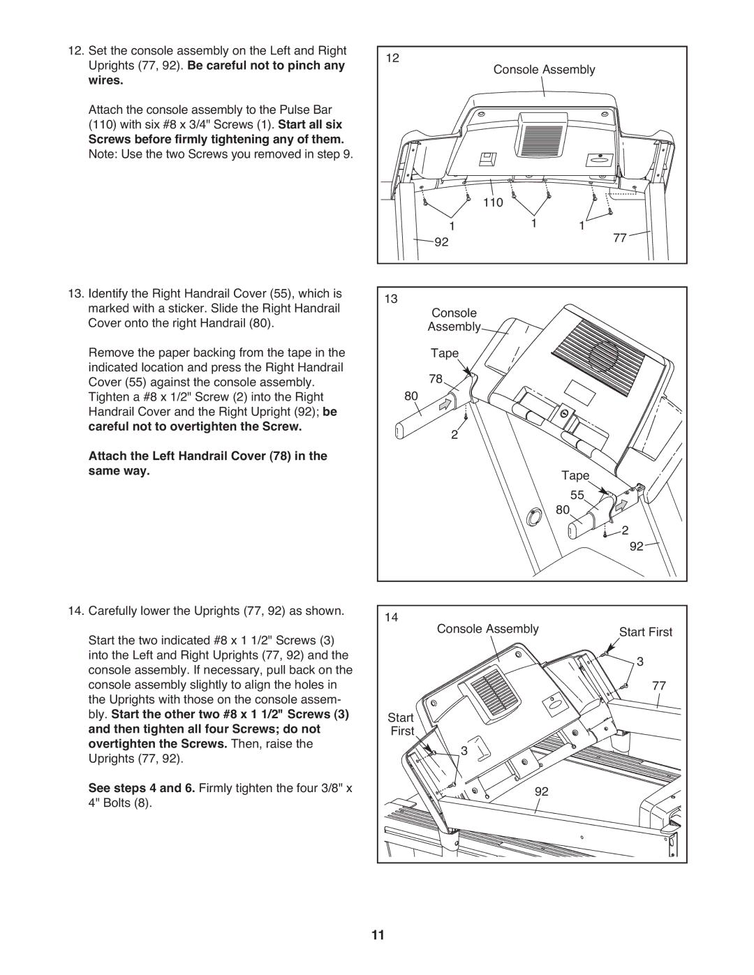
12. Set the console assembly on the Left and Right | 12 |
|
|
|
|
|
|
Uprights (77, 92). Be careful not to pinch any |
| Console Assembly |
|
| |||
wires. |
|
|
|
| |||
Attach the console assembly to the Pulse Bar |
|
|
|
|
|
|
|
(110) with six #8 x 3/4" Screws (1). Start all six |
|
|
|
|
|
|
|
Screws before firmly tightening any of them. |
|
|
|
|
|
|
|
Note: Use the two Screws you removed in step 9. |
|
|
|
|
|
|
|
|
| 921 | 110 | 1 | 1 | 77 |
|
|
|
|
| ||||
13. Identify the Right Handrail Cover (55), which is | 13 | Console |
|
|
|
|
|
marked with a sticker. Slide the Right Handrail |
|
|
|
|
| ||
Cover onto the right Handrail (80). |
| Assembly |
|
|
|
|
|
Remove the paper backing from the tape in the |
| Tape |
|
|
|
|
|
indicated location and press the Right Handrail |
| 78 |
|
|
|
|
|
Cover (55) against the console assembly. | 80 |
|
|
|
|
| |
Tighten a #8 x 1/2" Screw (2) into the Right |
|
|
|
|
|
| |
Handrail Cover and the Right Upright (92); be |
| 2 |
|
|
|
|
|
careful not to overtighten the Screw. |
|
|
|
|
|
| |
Attach the Left Handrail Cover (78) in the |
|
|
| Tape |
|
| |
same way. |
|
|
|
|
| ||
|
|
|
| 80 | 55 | 292 |
|
|
|
|
|
|
|
| |
14. Carefully lower the Uprights (77, 92) as shown. | 14 | Console Assembly |
| Start First | |||
Start the two indicated #8 x 1 1/2" Screws (3) |
|
| |||||
into the Left and Right Uprights (77, 92) and the |
|
|
|
|
| 3 |
|
console assembly. If necessary, pull back on the |
|
|
|
|
| 77 | |
console assembly slightly to align the holes in |
|
|
|
|
|
| |
the Uprights with those on the console assem- | Start |
|
|
|
|
|
|
bly. Start the other two #8 x 1 1/2" Screws (3) |
|
|
|
|
|
| |
and then tighten all four Screws; do not | First |
|
|
|
|
|
|
overtighten the Screws. Then, raise the |
| 3 |
|
|
|
|
|
Uprights (77, 92). |
|
| 92 |
|
|
| |
See steps 4 and 6. Firmly tighten the four 3/8" x |
|
|
|
|
|
| |
4" Bolts (8). |
|
|
|
|
|
|
|
| 11 |
|
|
|
|
|
|
