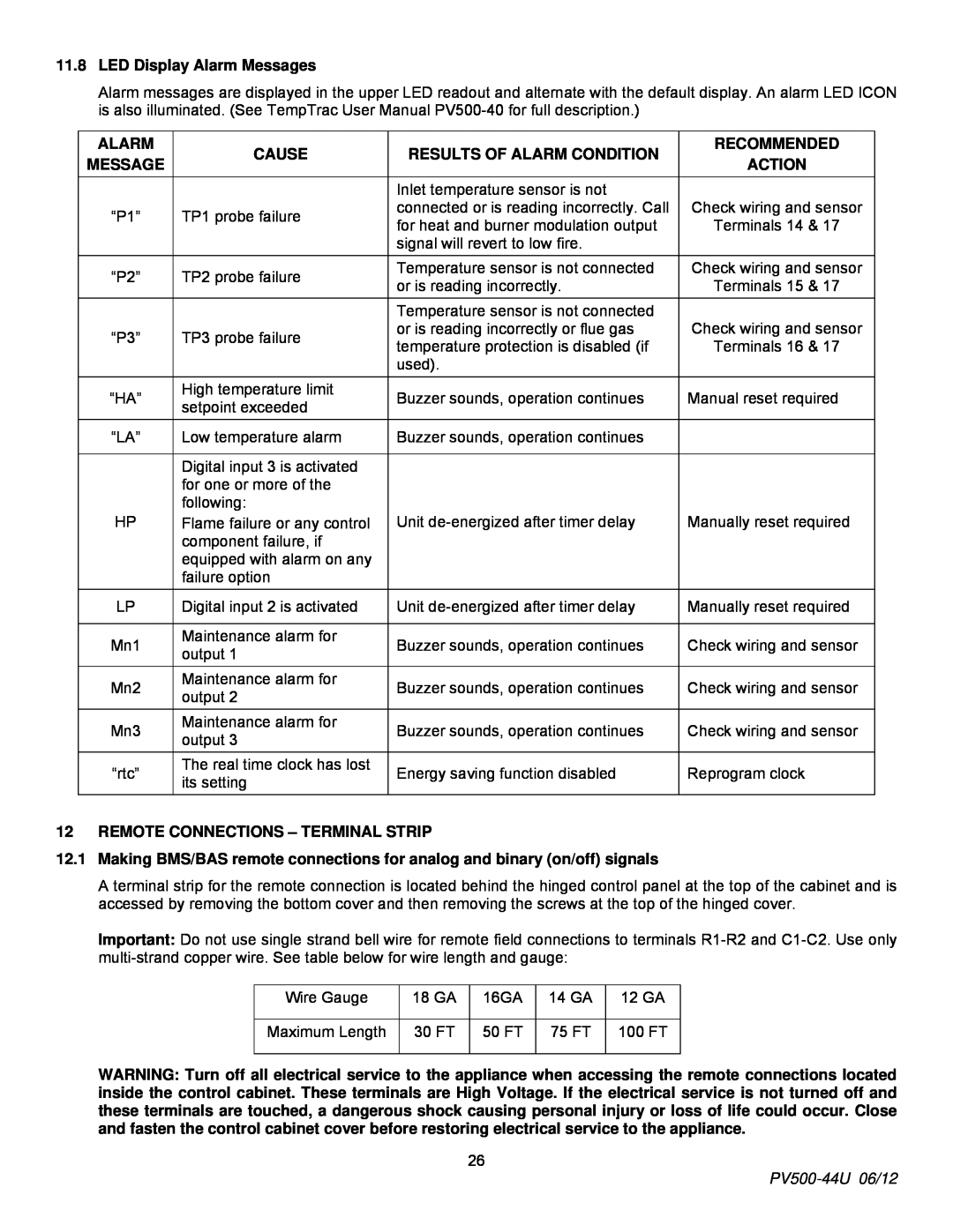
11.8LED Display Alarm Messages
Alarm messages are displayed in the upper LED readout and alternate with the default display. An alarm LED ICON is also illuminated. (See TempTrac User Manual
ALARM | CAUSE | RESULTS OF ALARM CONDITION | |
MESSAGE | |||
|
| ||
|
| Inlet temperature sensor is not | |
“P1” | TP1 probe failure | connected or is reading incorrectly. Call | |
for heat and burner modulation output | |||
|
| ||
|
| signal will revert to low fire. | |
|
|
| |
“P2” | TP2 probe failure | Temperature sensor is not connected | |
or is reading incorrectly. | |||
|
| ||
|
| Temperature sensor is not connected | |
“P3” | TP3 probe failure | or is reading incorrectly or flue gas | |
temperature protection is disabled (if | |||
|
| ||
|
| used). | |
|
|
| |
“HA” | High temperature limit | Buzzer sounds, operation continues | |
setpoint exceeded | |||
|
| ||
“LA” | Low temperature alarm | Buzzer sounds, operation continues | |
|
|
| |
| Digital input 3 is activated |
| |
| for one or more of the |
| |
HP | following: | Unit | |
Flame failure or any control | |||
| component failure, if |
| |
| equipped with alarm on any |
| |
| failure option |
| |
LP | Digital input 2 is activated | Unit | |
|
|
| |
Mn1 | Maintenance alarm for | Buzzer sounds, operation continues | |
output 1 | |||
|
| ||
Mn2 | Maintenance alarm for | Buzzer sounds, operation continues | |
output 2 | |||
|
| ||
Mn3 | Maintenance alarm for | Buzzer sounds, operation continues | |
output 3 | |||
|
| ||
“rtc” | The real time clock has lost | Energy saving function disabled | |
its setting | |||
|
|
RECOMMENDED
ACTION
Check wiring and sensor
Terminals 14 & 17
Check wiring and sensor
Terminals 15 & 17
Check wiring and sensor
Terminals 16 & 17
Manual reset required
Manually reset required
Manually reset required
Check wiring and sensor
Check wiring and sensor
Check wiring and sensor
Reprogram clock
12 | REMOTE CONNECTIONS – TERMINAL STRIP |
|
|
|
| ||
12.1 | Making BMS/BAS remote connections for analog and binary (on/off) signals | ||||||
| A terminal strip for the remote connection is located behind the hinged control panel at the top of the cabinet and is | ||||||
| accessed by removing the bottom cover and then removing the screws at the top of the hinged cover. | ||||||
| Important: Do not use single strand bell wire for remote field connections to terminals | ||||||
|
|
| |||||
|
|
|
|
|
|
|
|
|
| Wire Gauge | 18 GA | 16GA | 14 GA | 12 GA |
|
|
|
|
|
|
|
|
|
|
| Maximum Length | 30 FT | 50 FT | 75 FT | 100 FT |
|
|
|
|
|
|
|
|
|
WARNING: Turn off all electrical service to the appliance when accessing the remote connections located inside the control cabinet. These terminals are High Voltage. If the electrical service is not turned off and these terminals are touched, a dangerous shock causing personal injury or loss of life could occur. Close and fasten the control cabinet cover before restoring electrical service to the appliance.
26