Step 4. Install Transceivers
An SFP transceiver is required for each switch port that will be connected to a device.
❑To install an SFP transceiver, insert the transceiver into the switch port and gently press until it snaps in place. The transceiver will fit only one way. If the transceiver does not install under gentle pressure, flip it over and try again.
Step 5. Apply Power to the Switch
The maximum current requirements are 10 amps at 100 VAC or 4.2 amps at 240 VAC.
❑Attach the AC power cords to the Power Supply blades and wall outlets or power strips. Secure the strain relief bales to the plugs. Place the On/Off switches in the On position.
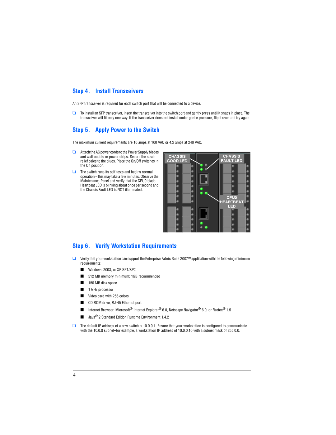
❑The switch runs its self tests and begins normal operation – this may take a few minutes. Observe the Maintenance Panel and verify that the CPU0 blade Heartbeat LED is blinking about once per second and the Chassis Fault LED is NOT illuminated.
CHASSIS |
| CHASSIS |
GOOD LED |
| FAULT LED |
CPU0
HEARTBEAT
LED
Step 6. Verify Workstation Requirements
❑Verify that your workstation can support the Enterprise Fabric Suite 2007™ application with the following minimum requirements:
■Windows 2003, or XP SP1/SP2
■512 MB memory minimum; 1GB recommended
■150 MB disk space
■1 GHz processor
■Video card with 256 colors
■CD ROM drive,
■Internet Browser: Microsoft® Internet Explorer® 6.0, Netscape Navigator® 6.0, or Firefox® 1.5
■Java® 2 Standard Edition Runtime Environment 1.4.2
❑The default IP address of a new switch is 10.0.0.1. Ensure that your workstation is configured to communicate with the 10.0.0
4