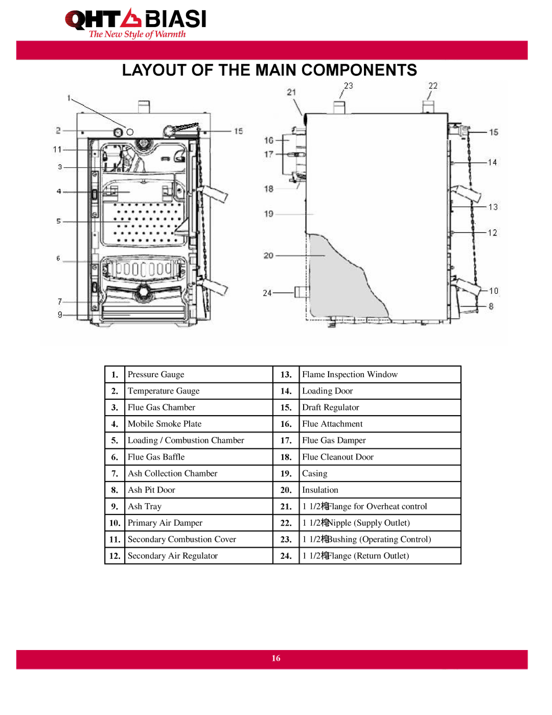
Boiler specifications
The QHT Boiler is an advanced heating solution designed for both residential and commercial applications. Known for its efficiency and innovative technology, the QHT Boiler has rapidly gained recognition in the industry for its unique features and superior performance.One of the main characteristics of the QHT Boiler is its high-efficiency rating. Utilizing cutting-edge technology, the boiler operates at a remarkably high thermal efficiency, which not only reduces energy consumption but also lowers operational costs for users. This efficiency is achieved through smart design and effective heat exchange systems that ensure maximum utilization of fuel.
Another notable feature of the QHT Boiler is its compact and space-saving design. Many models are engineered to be installed in tight spaces while still delivering powerful heating capabilities. This is especially valuable in urban environments where space is at a premium. The boiler’s sleek design also ensures that it can blend seamlessly with modern home aesthetics.
In terms of technology, the QHT Boiler incorporates advanced control systems that allow for precision temperature management. Users can easily set and adjust the desired temperatures through an intuitive interface, whether via a digital display or a mobile application. This flexibility ensures that heating needs are met efficiently, providing comfort without excess energy use.
Durability and reliability are key characteristics of the QHT Boiler. Constructed from high-quality materials, the boiler is designed to withstand the rigors of daily operation while minimizing the need for maintenance. This reliability is crucial for both homeowners and businesses, as it translates to reduced downtime and long-term cost savings.
Sustainability is another critical focus of the QHT Boiler’s design. Many models are compatible with renewable energy sources, including solar thermal systems, allowing users to reduce their carbon footprint. The incorporation of features like modulating burners helps to adjust the combustion process to varying heat demands, resulting in lower emissions.
Safety features are also paramount in the QHT Boiler’s design. It includes multiple safety mechanisms such as pressure relief valves and flame detection sensors to ensure safe operation. These features provide peace of mind to users, knowing that the boiler operates within safe parameters.
In summary, the QHT Boiler represents a fusion of efficiency, advanced technology, and user-friendly design, making it a top choice for heating solutions. With its compact size, high-efficiency rating, innovative control systems, and commitment to sustainability, the QHT Boiler stands out as a modern solution for diverse heating needs. Whether for residential or commercial use, it meets the demands of today’s energy-conscious consumers.

