Connections
The
HF INPUT Terminals
Connect the amplifier’s output signal to the loudspeaker’s HF INPUT terminals. Observe proper polarity; amplifier + signal to loud- speaker + HF INPUT, amplifier - signal to loudspeaker - HF INPUT. Use the largest wire size and shortest length for the application.
NOTE! Do not apply full range signal to the
HF OUTPUT Terminals
The HF OUTPUT terminals are
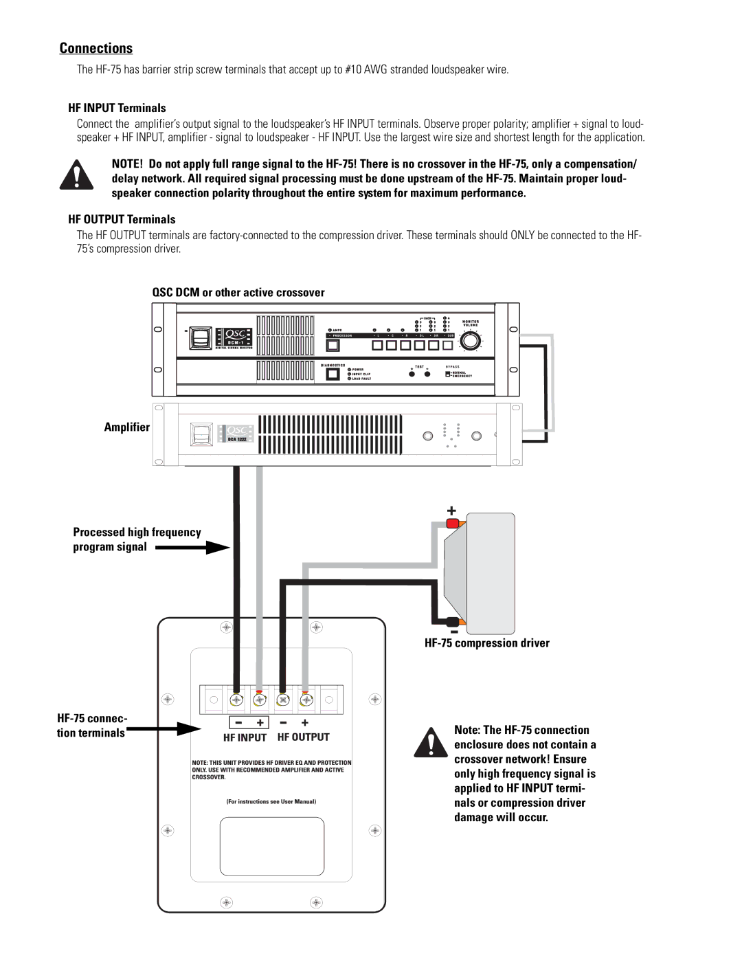
QSC DCM or other active crossover
Amplifier |
Processed high frequency program signal ![]()
HF-75 compression driver
HF-75 connec- tion terminals 
Note: The