7. External Connections
Terminal
DTE
Terminal
DTE
Modem
DCE
Telephone
line
Modem
DCE
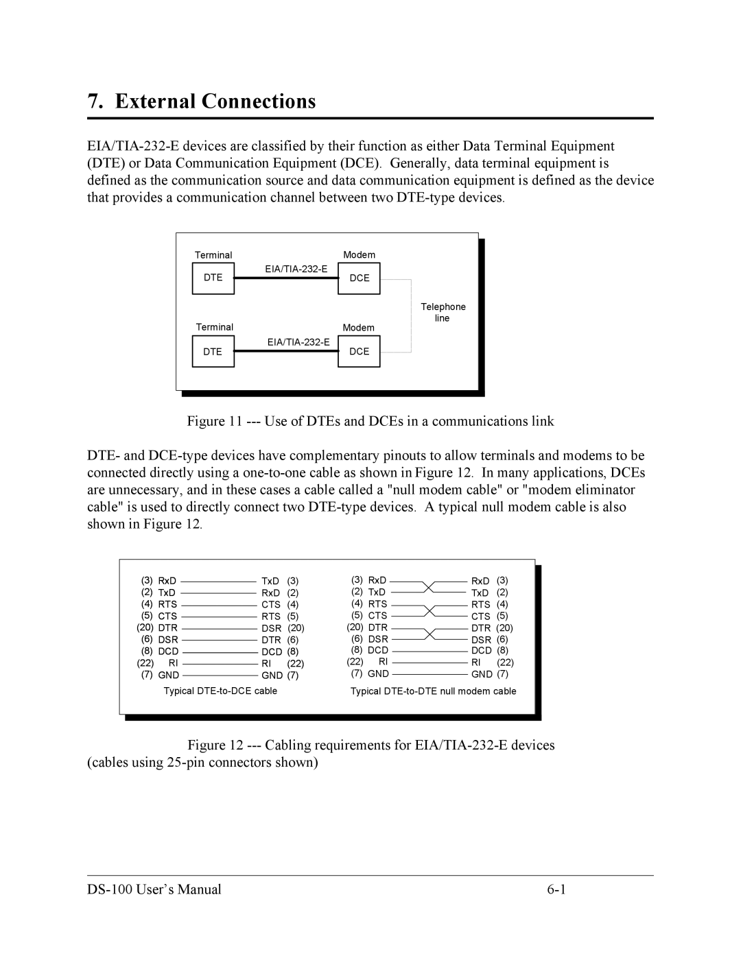
Figure 11 --- Use of DTEs and DCEs in a communications link
DTE- and DCE-type devices have complementary pinouts to allow terminals and modems to be connected directly using a one-to-one cable as shown in Figure 12. In many applications, DCEs are unnecessary, and in these cases a cable called a "null modem cable" or "modem eliminator cable" is used to directly connect two DTE-type devices. A typical null modem cable is also shown in Figure 12.
(3) | RxD |
|
|
|
|
| TxD | (3) | (3) | RxD |
| RxD | (3) |
|
|
| |||||||||||||
(2) | TxD |
|
|
|
|
| RxD | (2) | (2) | TxD |
| TxD | (2) |
|
|
| |||||||||||||
(4) | RTS |
|
|
|
|
| CTS | (4) | (4) | RTS |
| RTS | (4) |
|
(5) | CTS |
|
|
|
|
| RTS | (5) | (5) | CTS |
| CTS | (5) |
|
|
|
| ||||||||||||
(20) | DTR |
|
|
|
|
| DSR (20) | (20) DTR |
| DTR (20) |
| |||
|
|
|
| |||||||||||
(6) | DSR |
|
|
|
|
| DTR | (6) | (6) | DSR |
| DSR (6) |
| |
|
|
|
| |||||||||||
(8) | DCD |
|
|
|
|
| DCD (8) | (8) DCD |
| DCD (8) |
| |||
(22) | RI |
|
|
|
|
| RI | (22) | (22) | RI |
| RI | (22) |
|
|
|
|
|
|
| |||||||||
(7) | GND |
|
|
|
|
| GND (7) | (7) GND |
| GND (7) |
| |||
|
|
|
|
|
| |||||||||
| Typical |
| Typical |
| ||||||||||
|
|
|
|
|
|
|
|
|
|
|
|
|
|
|
|
|
|
|
|
|
|
|
|
|
|
|
|
|
|
Figure 12 --- Cabling requirements for EIA/TIA-232-E devices (cables using 25-pin connectors shown)
|