2.2 Signal Connections
The
2.3 Full-duplex/Half-duplex Operation
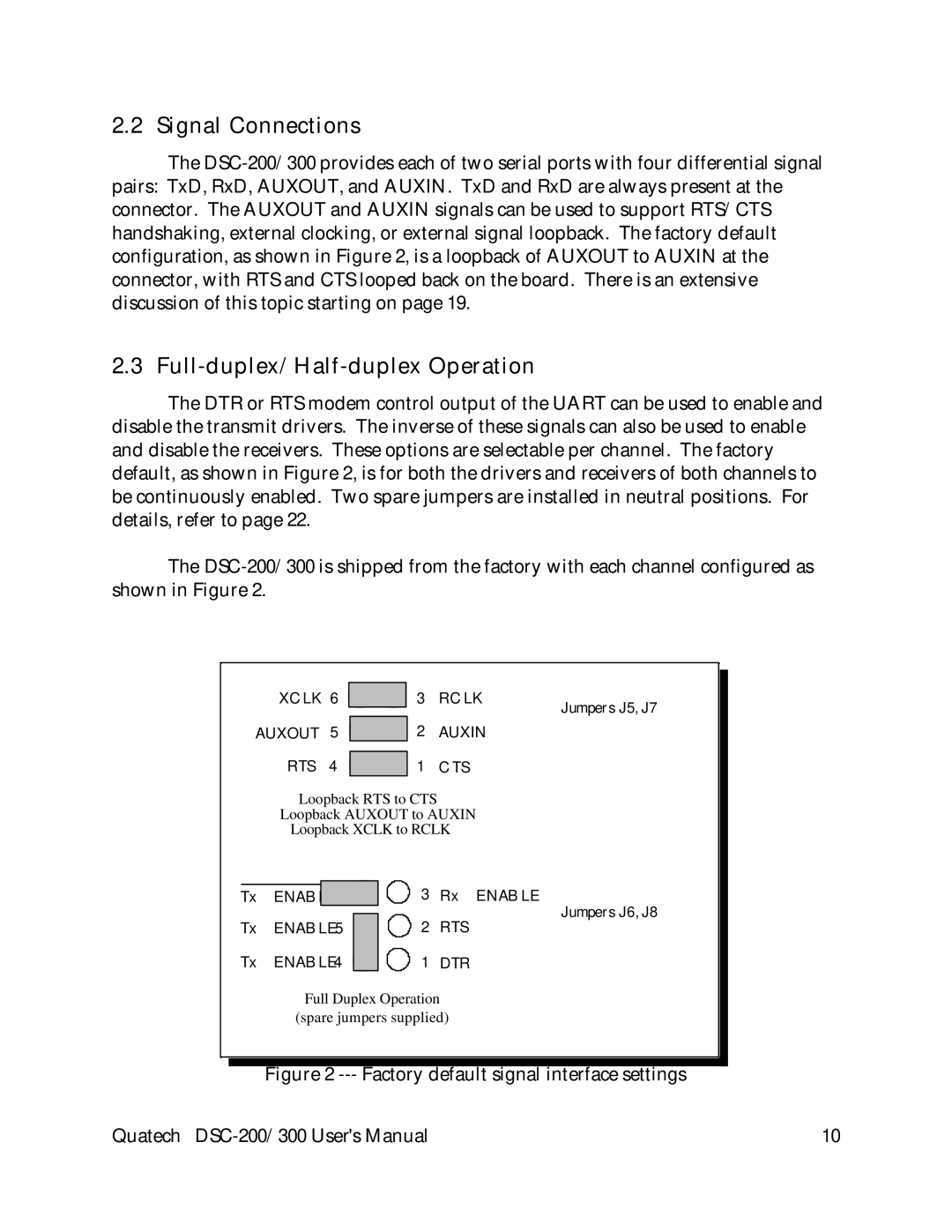
The DTR or RTS modem control output of the UART can be used to enable and disable the transmit drivers. The inverse of these signals can also be used to enable and disable the receivers. These options are selectable per channel. The factory default, as shown in Figure 2, is for both the drivers and receivers of both channels to be continuously enabled. Two spare jumpers are installed in neutral positions. For details, refer to page 22.
The
XCLK 6 ![]()
![]() 3 RCLK
3 RCLK
AUXOUT 5 ![]()
![]() 2 AUXIN
2 AUXIN
RTS 4 ![]()
![]() 1 CTS
1 CTS
Loopback RTS to CTS Loopback AUXOUT to AUXIN
Loopback XCLK to RCLK
Jumpers J5, J7
Tx ENABLE | 3 | Rx ENABLE | |
Tx | ENABLE5 | 2 | Jumpers J6, J8 |
RTS | |||
Tx | ENABLE4 | 1 | DTR |
Full Duplex Operation
(spare jumpers supplied)
Figure 2 --- Factory default signal interface settings
Quatech | 10 |