Quatech DSC-200/300 user manual External Connections, Jumper/Channel correspondence

Models: DSC-200/300

1 39
Download 39 pages 24.96 Kb
Page 29
Image 29

8 External Connections

The DSC-200/300 provides four differential communication signals per channel. The two output signals are Transmit Data (TxD) and Auxiliary Output (AUXOUT). The two input signals are Receive Data (RxD) and Auxiliary Input (AUXIN). A ground signal is also provided.

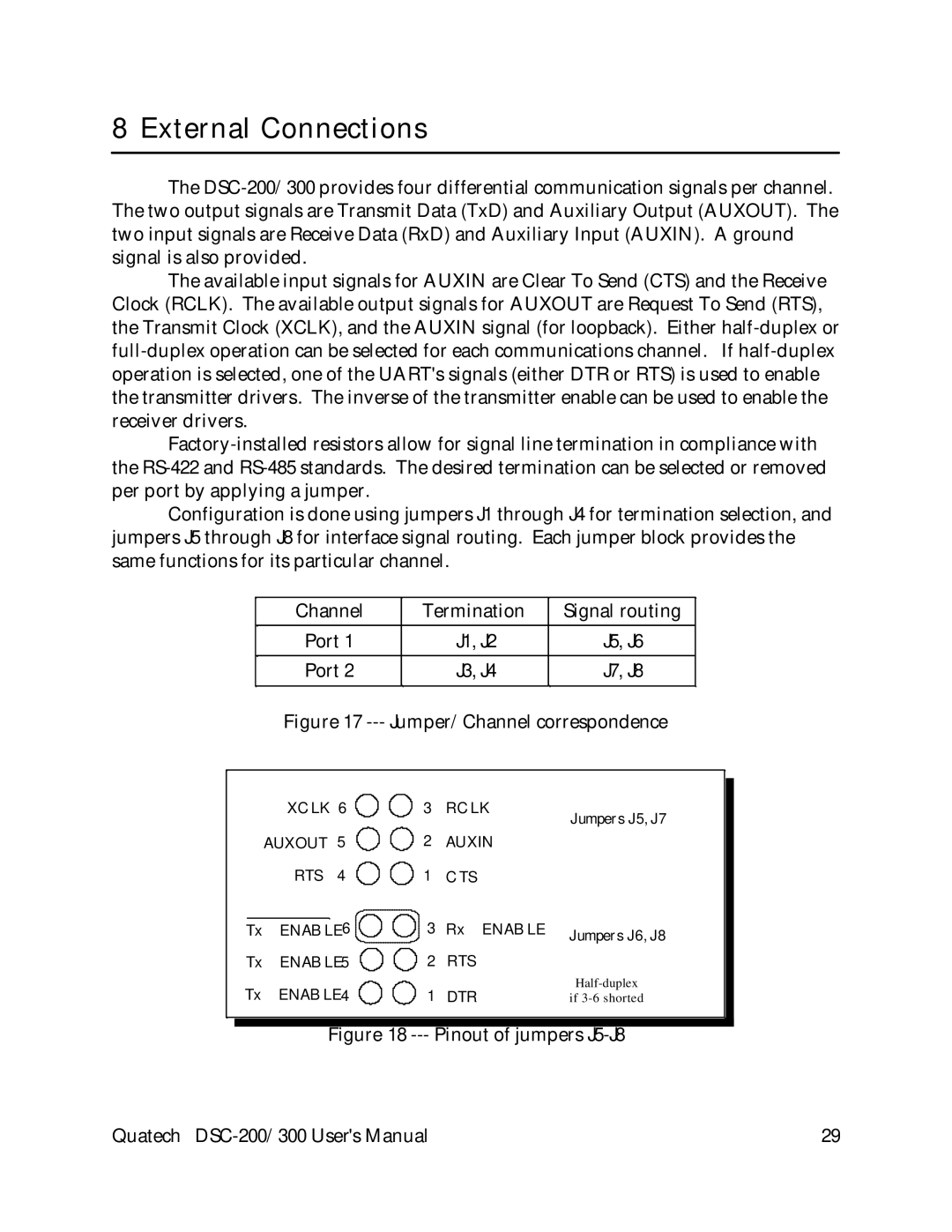
The available input signals for AUXIN are Clear To Send (CTS) and the Receive Clock (RCLK). The available output signals for AUXOUT are Request To Send (RTS), the Transmit Clock (XCLK), and the AUXIN signal (for loopback). Either half-duplex or full-duplex operation can be selected for each communications channel. If half-duplex operation is selected, one of the UART's signals (either DTR or RTS) is used to enable the transmitter drivers. The inverse of the transmitter enable can be used to enable the receiver drivers.

Factory-installed resistors allow for signal line termination in compliance with the RS-422 and RS-485 standards. The desired termination can be selected or removed per port by applying a jumper.

Configuration is done using jumpers J1 through J4 for termination selection, and jumpers J5 through J8 for interface signal routing. Each jumper block provides the same functions for its particular channel.

Channel

Termination

Signal routing


Port 1

J1, J2

J5, J6


Port 2

J3, J4

J7, J8


Figure 17 --- Jumper/Channel correspondence

XCLK 6

3

RCLK

Jumpers J5, J7


AUXOUT 5

2

AUXIN


RTS 4

1

CTS


Tx ENABLE6

3

Rx ENABLE

Jumpers J6, J8

Tx ENABLE5

2

RTS


Tx ENABLE4

1

DTR

Half-duplex

if 3-6 shorted

Figure 18 --- Pinout of jumpers J5-J8

Quatech DSC-200/300 User's Manual

29

Page 29
Image 29
Quatech DSC-200/300 user manual External Connections, Jumper/Channel correspondence