3Hardware Installation
1.Turn off the power of the computer system in which the
2.Remove the system cover according to the instructions provided by the computer manufacturer.
3.Make any desired optional jumper setting changes.
4.Install the
5.Replace the system cover according to the instructions provided by the computer manufacturer.
6.Attach and secure the cable connectors to the desired equipment.
7.Turn on the power of the computer system.
The output of the
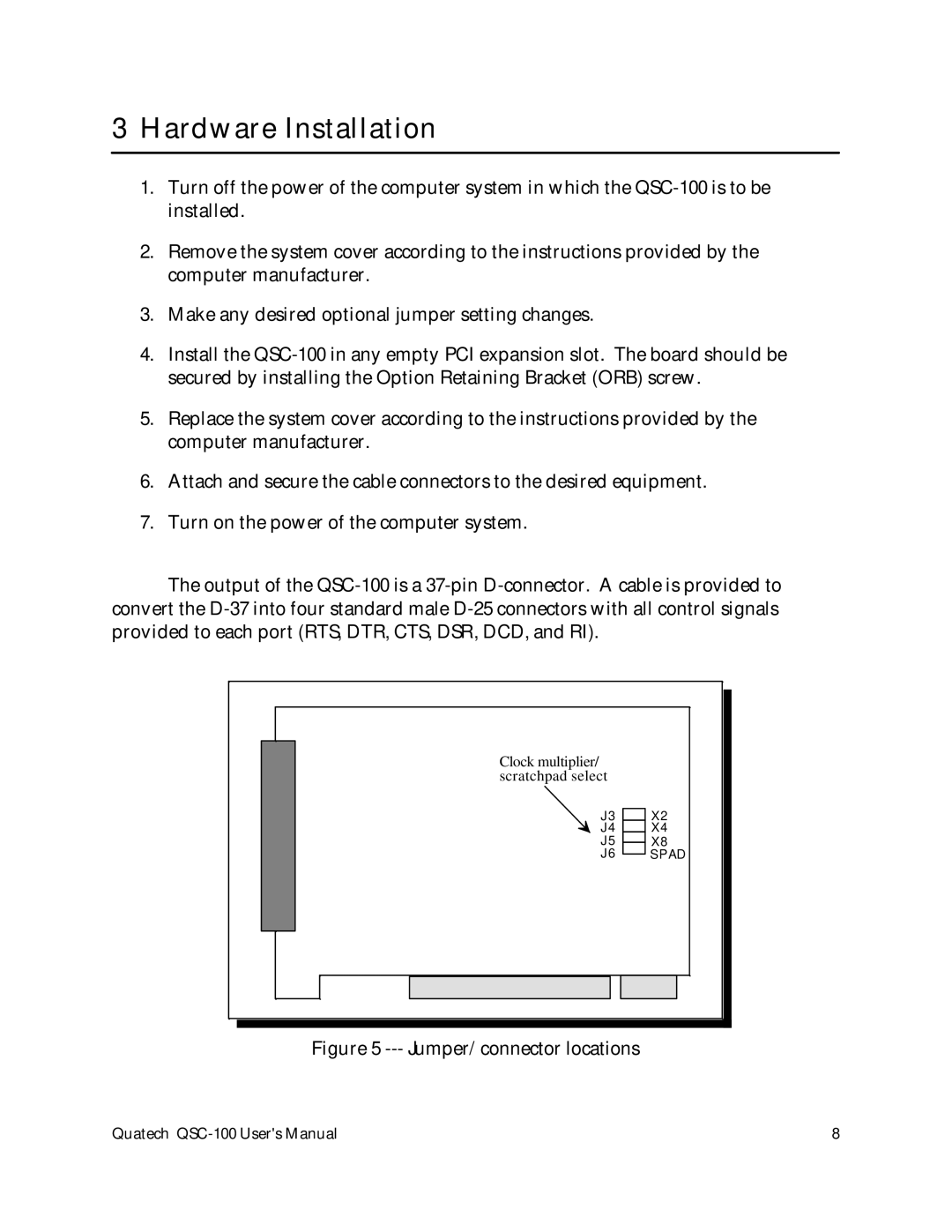
Clock multiplier/ |
|
scratchpad select |
|
J3 | X2 |
J4 | X4 |
J5 | X8 |
J6 | SPAD |
Figure 5 |
|
Quatech | 8 |