Manuals
/
RAD Data comm
/
Computer Equipment
/
Network Router
RAD Data comm
specifications
Installation, Configuring TinyBridge-100, DIP Switch Settings
Models:
100
1
7
9
9
Download
9 pages
25.47 Kb
2
3
4
5
6
7
8
9
Page 7
Image 7
Page 6
Page 8
Page 7
Image 7
Page 6
Page 8
Contents
Ethernet Bridge
ORDERING
TinyBridge-100
Miniature Remote Fast
DESCRIPTION
FEATURES
Wire-speed WAN throughput 19,700 pps at 10 Mbps 10/100BaseT interface
Fault propagation of WAN error conditions to LAN port
FLAG
Figure 2. Receive and Transmit Clock Timing Diagrams
APPLICATIONS
5ns 5ns
Figure 6. Broadcasting Data over Satellite Link
SPECIFICATIONS
Figure 5. Extending Ethernet over 4-Wires in the Campus Enviroment
ETHERNET
Power Supply
SAFETY
4-wire Range
Connectors
declares that the product
Sicherheitshinweise
ACHTUNG
DECLARATION OF CONFORMITY
Connecting the LAN Interface
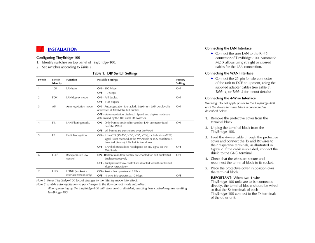
INSTALLATION
Configuring TinyBridge-100
Table 1. DIP Switch Settings
Table 3. DB-25 Pin Allocation
Table 2. LED Indicators
Figure 7. Connecting the 4-wire WAN Interface Connecting Power
OPERATION
used for RS-530, X.21
Table 4. DB-25 Pin Allocation V.35
Table 5. DB-25 Pin Allocation
V.11
Top
Page
Image
Contents