|
| 15 | /16 | ||||
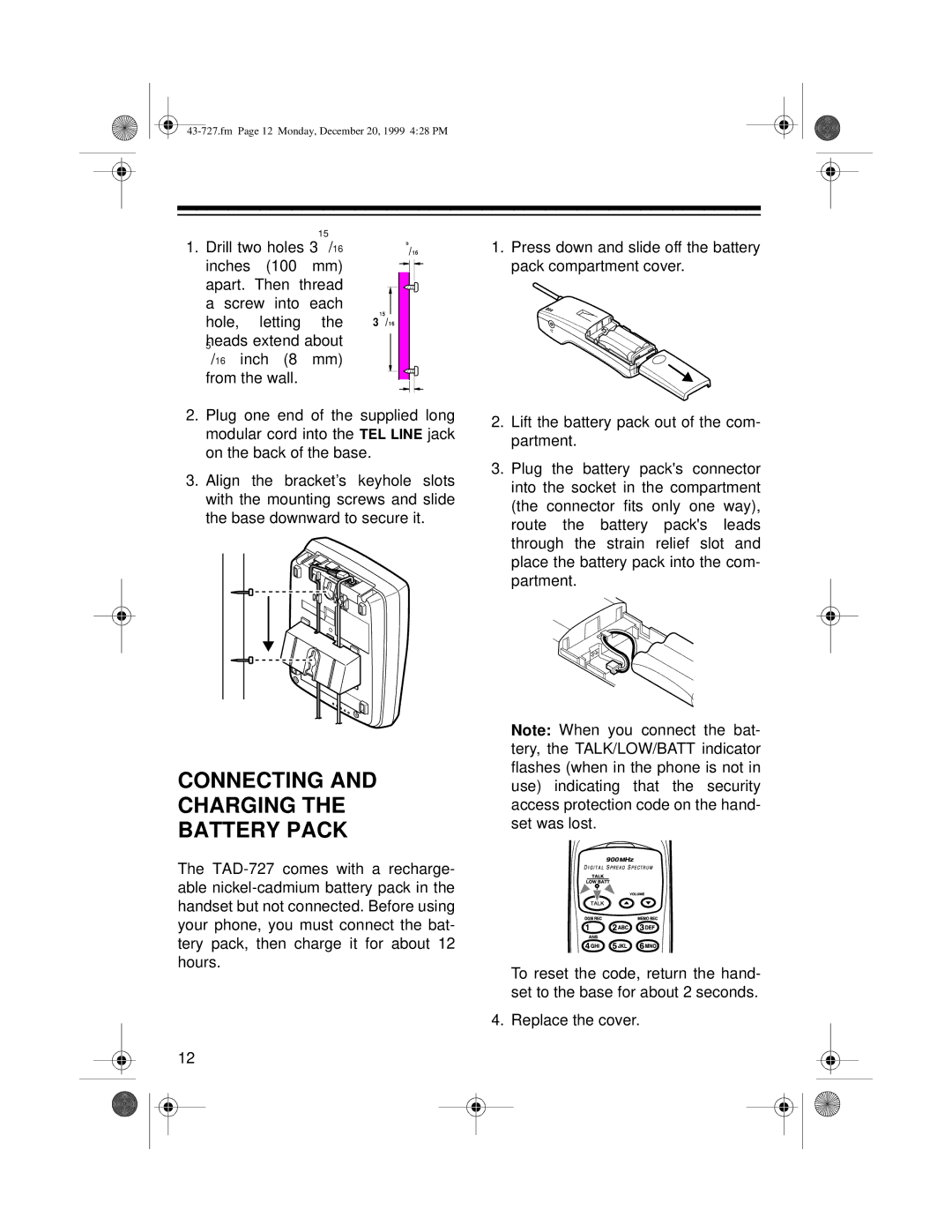
1. Drill two holes 3 /16 | |||||||
|
|
| 5 |
|
| ||
inches | (100 | mm) |
|
|
|
|
|
|
|
|
|
| |||
apart. Then thread |
|
|
|
|
| ||
|
|
|
|
| |||
a screw into | each | 15 |
|
|
|
| |
hole, | letting | the |
|
|
|
| |
3 /16 |
|
|
| ||||
5heads extend about |
|
|
|
|
| ||
|
|
|
|
| |||
/16 inch (8 mm) |
|
|
|
|
| ||
from the wall. |
|
|
|
|
|
| |
|
|
|
|
|
| ||
|
|
|
|
|
|
|
|
2.Plug one end of the supplied long modular cord into the TEL LINE jack on the back of the base.
3.Align the bracket’s keyhole slots with the mounting screws and slide the base downward to secure it.
CONNECTING AND
CHARGING THE
BATTERY PACK
The
12
1.Press down and slide off the battery pack compartment cover.
2.Lift the battery pack out of the com- partment.
3.Plug the battery pack's connector into the socket in the compartment (the connector fits only one way), route the battery pack's leads through the strain relief slot and place the battery pack into the com- partment.
Note: When you connect the bat- tery, the TALK/LOW/BATT indicator flashes (when in the phone is not in use) indicating that the security access protection code on the hand- set was lost.
To reset the code, return the hand- set to the base for about 2 seconds.
4. Replace the cover.
