Manuals
/
Ramsey Electronics
/
TV and Video
/
Universal Remote
Ramsey Electronics
manual
RR1 Parts Placement Diagram
Models:
RR1
1
17
20
20
Download
20 pages
58.05 Kb
13
14
15
16
17
18
19
20
Troubleshooting
Specifications
RR1 Parts Placement Diagram
Warranty
Testing the RR1
Using the RR1
Page 17
Image 17
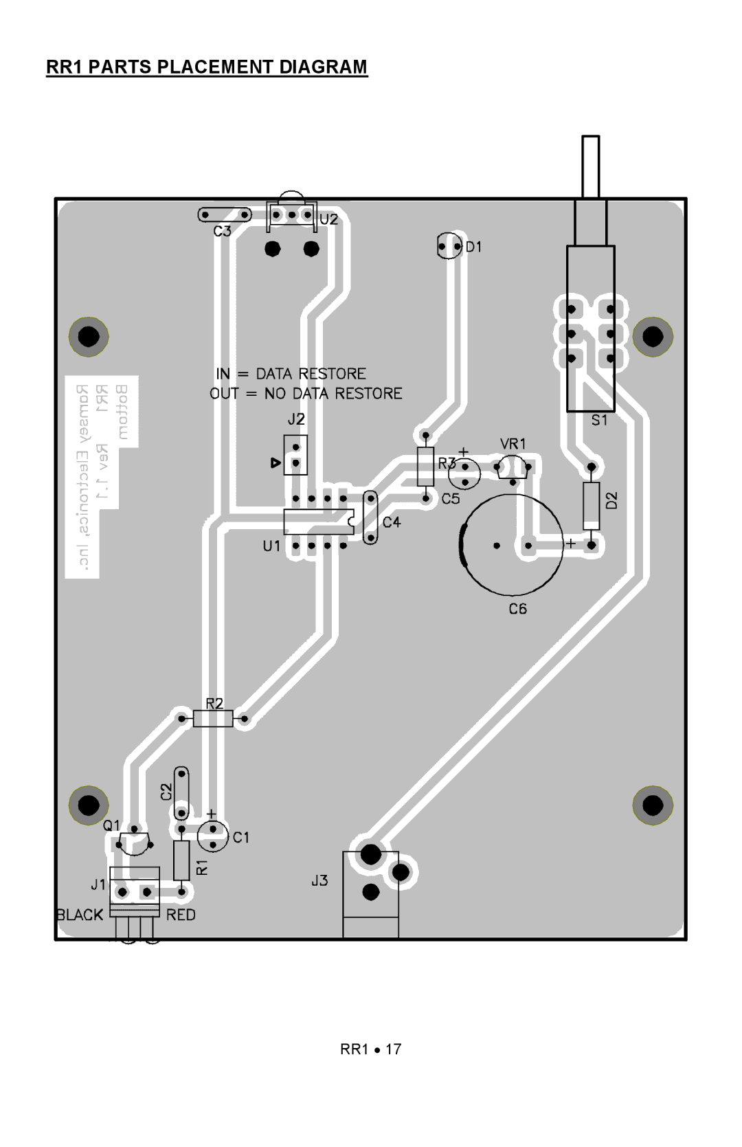
RR1 PARTS PLACEMENT DIAGRAM
RR1
•
17
Page 16
Page 18
Page 17
Image 17
Page 16
Page 18
Contents
Ramsey Electronics Model No. RR1
Ramsey Transmitter Kits
RR1 Remote Repeater KIT
RR1 Introduction
RR1 Theory of Operation
Output
RR1
Kit building tips
Ramsey LEARN-AS-YOU-BUILD Assembly Strategy
RR1
Capacitors
Parts Supplied with Your RR1 KIT
RR1 Remote Repeater KIT Assembly
RR1
RR1
Testing the RR1
Using the RR1
Troubleshooting Guide
RR1
RR1 Parts Placement Diagram
RR1 Specifications
Ramsey Kit Warranty
RR1 Remote Repeater KIT
Total Solder Points Estimated Assembly Time
Required Tools
Additional Suggested Items
Top
Page
Image
Contents