10. Install J2, the
11. Install C4, a 0.1 uF ceramic capacitor (marked .1 or 104 or 100 nF).
12. Install R3, a 220 ohm resistor
13. Install C5, a 10 uF electrolytic capacitor. Again check orientation before soldering into place.
14. Install VR1, the 78L05 voltage regulator. Make sure the flat side of this component is orientated the same direction as shown on the silk screen. This part works by “smoothing” out any junk that may reside on the non- regulated input side of the part. It also allows you to run this kit from a wide range of supply voltages on the input, while it keeps the output to 5V.
15. Install C6, the large 1000 uF electrolytic capacitor. Double check the orientation before soldering as this is especially critical with this component.
16. Install D2, a 1N4002 regulator diode. This diode helps to convert AC from a “wall wart” AC transformer to pulsed DC. C6 accumulates the pulsed DC and smoothes it out a bit. VR1 then smoothes it out the rest of the way to make for a nice, clean power source. Make sure the line which indicates the cathode is installed in the same orientation as shown on the silk screen.
17. Install C3, a 0.1 uF ceramic capacitor (marked .1 or 104 or 100 nF).
18. Install U2, the IR detector IC. Make sure and mount it as shown and that you solder the mechanical mounting pins as well as the electrical pins.
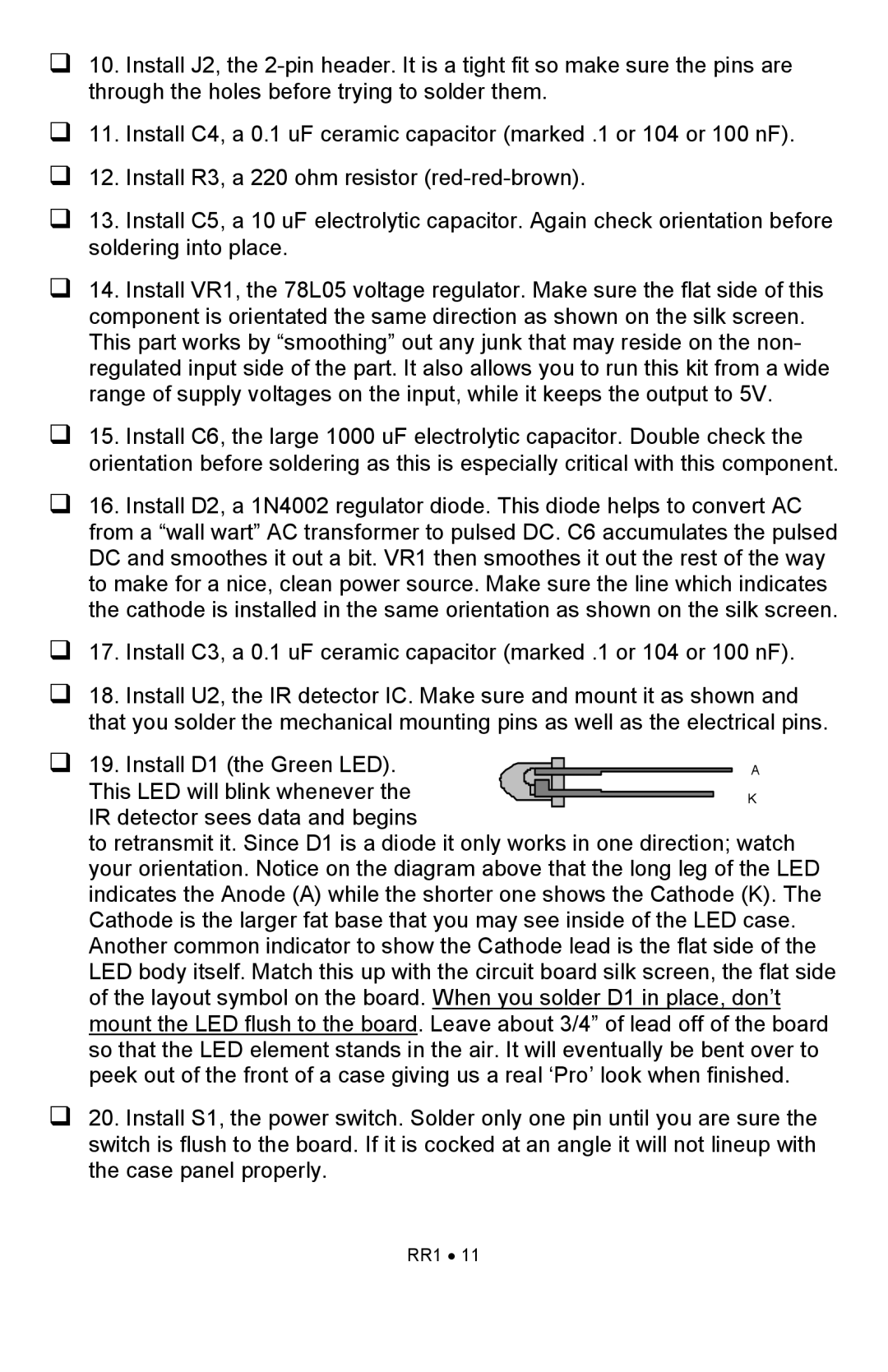
19. Install D1 (the Green LED). |
|
|
|
|
|
| A |
|
|
| |||||
This LED will blink whenever the |
|
|
|
|
|
| K |
|
|
|
| ||||
|
|
|
|
|
| ||
IR detector sees data and begins |
|
|
|
| |||
|
|
|
| ||||
to retransmit it. Since D1 is a diode it only works in one direction; watch your orientation. Notice on the diagram above that the long leg of the LED indicates the Anode (A) while the shorter one shows the Cathode (K). The Cathode is the larger fat base that you may see inside of the LED case. Another common indicator to show the Cathode lead is the flat side of the LED body itself. Match this up with the circuit board silk screen, the flat side of the layout symbol on the board. When you solder D1 in place, don’t mount the LED flush to the board. Leave about 3/4” of lead off of the board so that the LED element stands in the air. It will eventually be bent over to peek out of the front of a case giving us a real ‘Pro’ look when finished.
20. Install S1, the power switch. Solder only one pin until you are sure the switch is flush to the board. If it is cocked at an angle it will not lineup with the case panel properly.