RR1 THEORY OF OPERATION
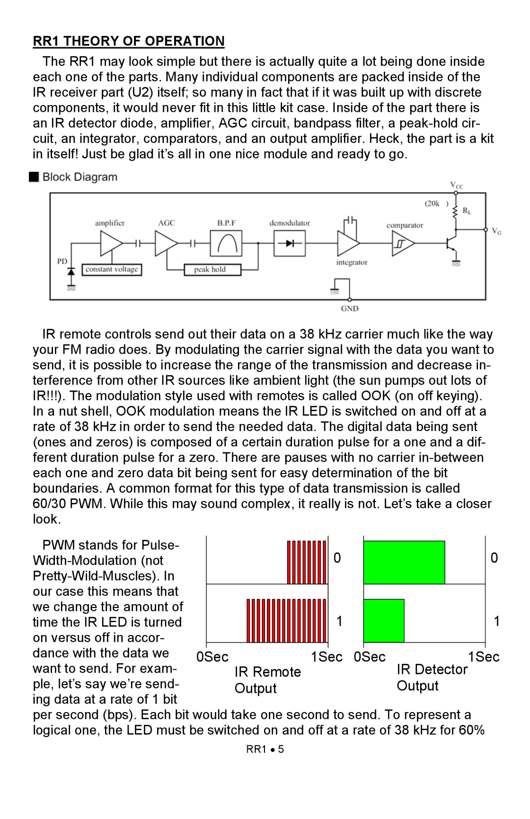
The RR1 may look simple but there is actually quite a lot being done inside each one of the parts. Many individual components are packed inside of the IR receiver part (U2) itself; so many in fact that if it was built up with discrete components, it would never fit in this little kit case. Inside of the part there is an IR detector diode, amplifier, AGC circuit, bandpass filter, a
IR remote controls send out their data on a 38 kHz carrier much like the way your FM radio does. By modulating the carrier signal with the data you want to send, it is possible to increase the range of the transmission and decrease in- terference from other IR sources like ambient light (the sun pumps out lots of IR!!!). The modulation style used with remotes is called OOK (on off keying). In a nut shell, OOK modulation means the IR LED is switched on and off at a rate of 38 kHz in order to send the needed data. The digital data being sent (ones and zeros) is composed of a certain duration pulse for a one and a dif- ferent duration pulse for a zero. There are pauses with no carrier
PWM stands for Pulse- |
|
|
|
|
|
|
|
|
|
|
|
|
|
|
|
|
|
| 0 |
|
|
|
| 0 |
|
|
|
|
|
|
|
|
|
|
|
|
|
|
|
|
|
|
|
|
|
| |||
|
|
|
|
|
|
|
|
|
|
|
|
|
|
|
|
|
|
|
|
|
| |||
|
|
|
|
|
|
|
|
|
|
|
|
|
|
|
|
|
|
|
|
|
|
|
| |
our case this means that |
|
|
|
|
|
|
|
|
|
|
|
|
|
|
|
|
|
|
|
|
|
|
|
|
we change the amount of |
|
|
|
|
|
|
|
|
|
|
|
|
|
|
|
|
|
| 1 |
|
|
|
| 1 |
time the IR LED is turned |
|
|
|
|
|
|
|
|
|
|
|
|
|
|
|
|
|
|
|
|
|
| ||
on versus off in accor- |
|
|
|
|
|
|
|
|
|
|
|
|
|
|
|
|
|
|
|
|
|
|
|
|
dance with the data we | 0Sec IR Remote |
| 1Sec 0Sec | IR Detector1Sec | ||||||||||||||||||||
want to send. For exam- |
| |||||||||||||||||||||||
ple, let’s say we’re send- |
| Output |
|
|
|
|
|
|
| Output | ||||||||||||||
ing data at a rate of 1 bit |
|
|
|
|
|
|
|
|
|
|
|
|
|
|
|
|
|
|
|
|
|
|
|
|
per second (bps). Each bit would take one second to send. To represent a logical one, the LED must be switched on and off at a rate of 38 kHz for 60%
RR1 • 5