Chapter 3: Installation | 13 | ||||||||||||||||||
|
|
|
|
|
|
|
|
|
|
|
|
|
|
|
|
|
|
|
|
|
|
|
|
|
|
|
|
|
|
|
|
|
|
|
|
|
|
|
|
|
|
|
|
|
|
|
|
|
|
|
|
|
|
|
|
|
|
|
|
|
|
|
|
|
|
|
|
|
|
|
|
|
|
|
|
|
|
|
|
|
|
|
|
|
|
|
|
|
|
|
|
|
|
|
|
|
|
|
|
|
|
|
|
|
|
|
|
|
|
|
|
|
|
|
|
|
|
|
|
|
|
|
|
|
|
|
|
|
|
|
|
|
|
|
|
|
|
|
|
57 mm
(2.25 in)
Note: If you intend fitting a nonstandard transducer, extra tools may be required.
Site requirements
Fluxgate Compass transducer
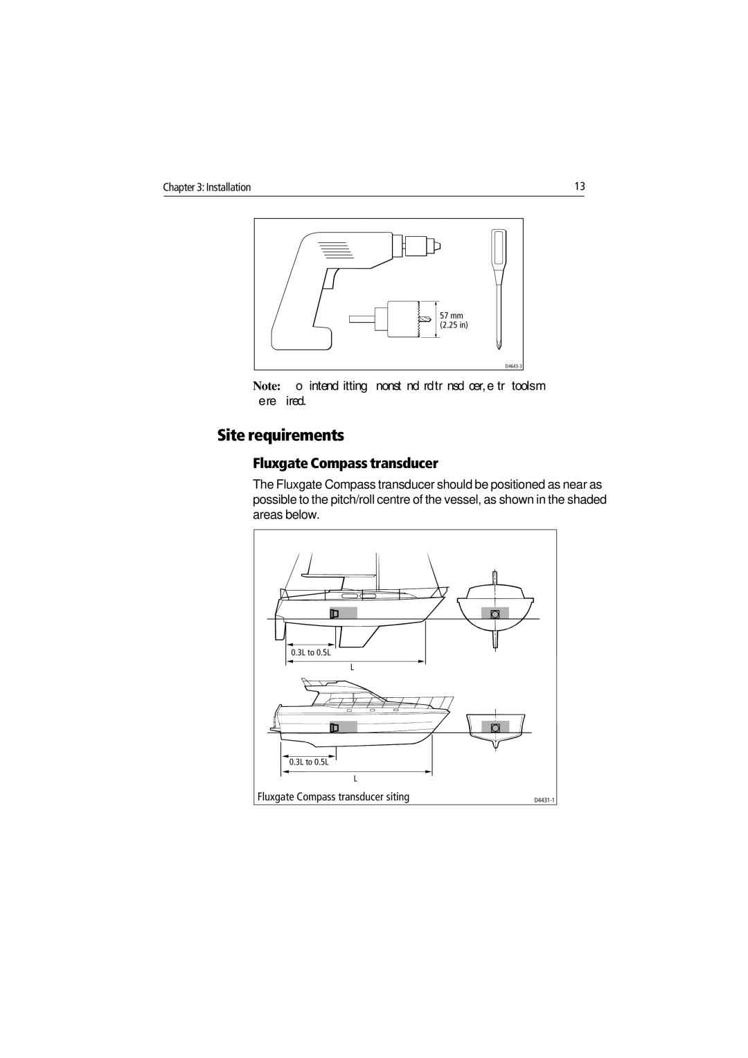
The Fluxgate Compass transducer should be positioned as near as possible to the pitch/roll centre of the vessel, as shown in the shaded areas below.
0.3L to 0.5L
L
0.3L to 0.5L
L
Fluxgate Compass transducer siting |
