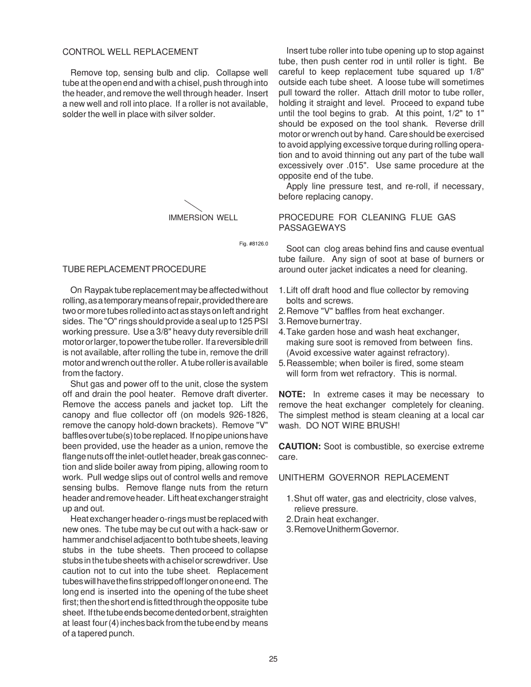
CONTROL WELL REPLACEMENT
Remove top, sensing bulb and clip. Collapse well tube at the open end and with a chisel, push through into the header, and remove the well through header. Insert a new well and roll into place. If a roller is not available, solder the well in place with silver solder.
IMMERSION WELL
Fig. #8126.0
TUBE REPLACEMENT PROCEDURE
On Raypak tube replacement may be affected without rolling,asa temporary meansofrepair, providedthereare two or more tubes rolled into act as stays on left and right sides. The "O" rings should provide a seal up to 125 PSI working pressure. Use a 3/8" heavy duty reversible drill motor or larger, to power the tube roller. If a reversible drill is not available, after rolling the tube in, remove the drill motor and wrench out the roller. A tube roller is available from the factory.
Shut gas and power off to the unit, close the system off and drain the pool heater. Remove draft diverter. Remove the access panels and jacket top. Lift the canopy and flue collector off (on models
Heat exchanger header
Insert tube roller into tube opening up to stop against tube, then push center rod in until roller is tight. Be careful to keep replacement tube squared up 1/8" outside each tube sheet. A loose tube will sometimes pull toward the roller. Attach drill motor to tube roller, holding it straight and level. Proceed to expand tube until the tool begins to grab. At this point, 1/2" to 1" should be exposed on the tool shank. Reverse drill motor or wrench out by hand. Care should be exercised to avoid applying excessive torque during rolling opera- tion and to avoid thinning out any part of the tube wall excessively over .015". Use same procedure at the opposite end of the tube.
Apply line pressure test, and
PROCEDURE FOR CLEANING FLUE GAS PASSAGEWAYS
Soot can clog areas behind fins and cause eventual tube failure. Any sign of soot at base of burners or around outer jacket indicates a need for cleaning.
1.Lift off draft hood and flue collector by removing bolts and screws.
2.Remove "V" baffles from heat exchanger. 3.Remove burner tray.
4.Take garden hose and wash heat exchanger, making sure soot is removed from between fins. (Avoid excessive water against refractory).
5.Reassemble; when boiler is fired, some steam will form from wet refractory. This is normal.
NOTE: In extreme cases it may be necessary to remove the heat exchanger completely for cleaning. The simplest method is steam cleaning at a local car wash. DO NOT WIRE BRUSH!
CAUTION: Soot is combustible, so exercise extreme care.
UNITHERM GOVERNOR REPLACEMENT
1.Shut off water, gas and electricity, close valves, relieve pressure.
2.Drain heat exchanger. 3.RemoveUnithermGovernor.
25