TOC
TOC
TROUBLESHOOTING & REPAIR |
TEST AFTER SWITCH BOARD OR CAPACITOR REPLACEMENT (cont.)
Return to Section
Return to Section TOC
Return to Master
Return to Master TOC
TEST PROCEDURE
1.Turn main power OFF.
2.Perform Input Filter Capacitor
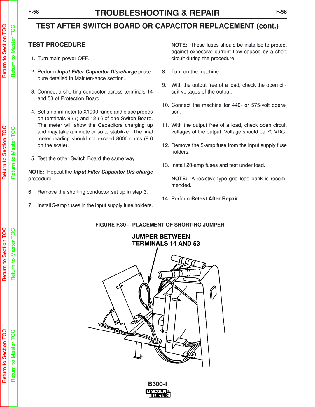
3.Connect a shorting conductor across terminals 14 and 53 of Protection Board.
4.Set an ohmmeter to X1000 range and place probes on terminals 9 (+) and 12
5.Test the other Switch Board the same way.
NOTE: Repeat the Input Filter Capacitor
6.Remove the shorting conductor set up in step 3.
7.Install
NOTE: These fuses should be installed to protect against excessive current flow caused by a short circuit during the procedure.
8.Turn on the machine.
9.With the output free of a load, check the open cir- cuit voltages of the output.
10.Connect the machine for 440- or
11.With the output free of a load, check open circuit voltages of the output. Voltage should be 70 VDC.
12.Remove the
13.Install
NOTE: A
14.Perform Retest After Repair.
Return to Section TOC
Return to Section TOC
Return to Master TOC
Return to Master TOC