Section TOC
Master TOC
TROUBLESHOOTING & REPAIR |
OUTPUT DIODE TEST (cont.)
TEST PROCEDURE
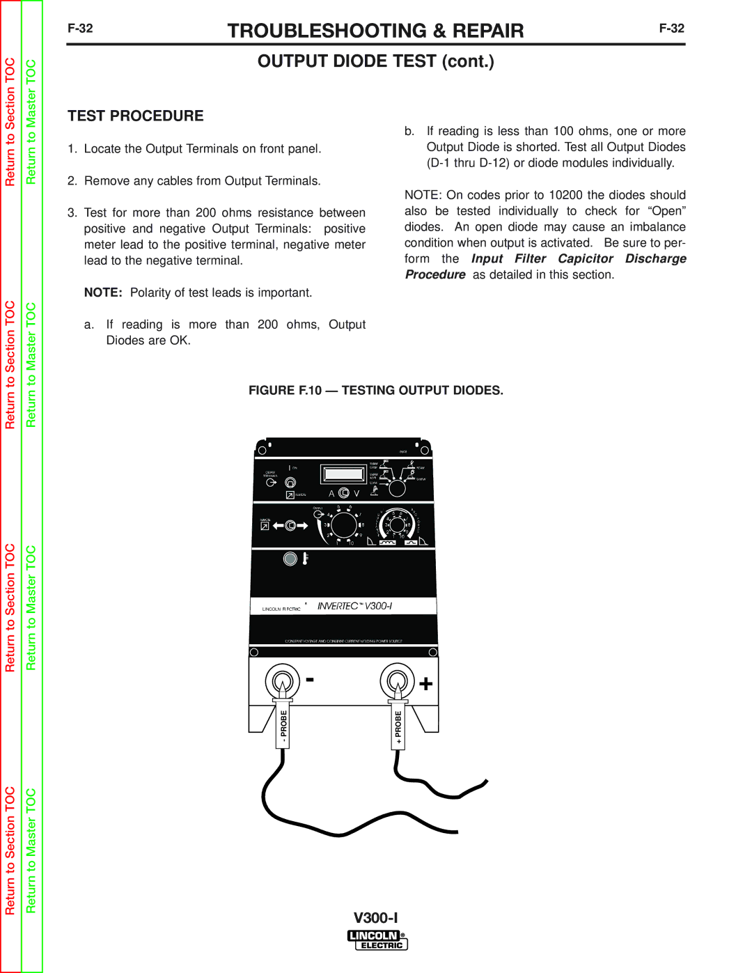
1.Locate the Output Terminals on front panel.
2.Remove any cables from Output Terminals.
3.Test for more than 200 ohms resistance between positive and negative Output Terminals: positive meter lead to the positive terminal, negative meter lead to the negative terminal.
NOTE: Polarity of test leads is important.
a.If reading is more than 200 ohms, Output Diodes are OK.
b.If reading is less than 100 ohms, one or more Output Diode is shorted. Test all Output Diodes
NOTE: On codes prior to 10200 the diodes should also be tested individually to check for “Open” diodes. An open diode may cause an imbalance condition when output is activated. Be sure to per- form the Input Filter Capicitor Discharge Procedure as detailed in this section.
Return
Return to Section TOC
Return to Section TOC
Return
Return to Master TOC
Return to Master TOC
FIGURE F.10 — TESTING OUTPUT DIODES.
LINCOLN
- +
|
|
|
|
|
|
|
|
|
|
|
|
|
|
|
|
|
| - PROBE |
|
|
|
|
|
| + PROBE |
|
| ||
|
|
|
|
|
|
|
|
|
|
|
|
|
|
|
|
|
|
|
|
|
|
|
|
|
|
|
|
|
|