Return to Section TOC
Section TOC
Return to Master TOC
Master TOC
TROUBLESHOOTING & REPAIR |
INPUT RECTIFIER TEST
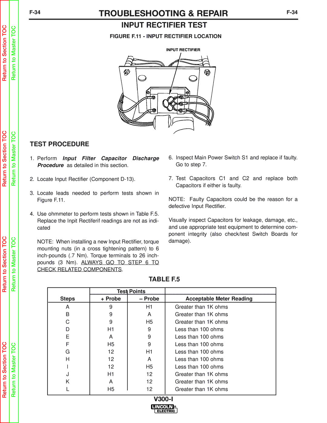
FIGURE F.11 - INPUT RECTIFIER LOCATION
TEST PROCEDURE
Return to
to Section TOC
Return to
to Master TOC
1.Perform Input Filter Capacitor Discharge Procedure as detailed in this section.
2.Locate Input Rectifier (Component
3.Locate leads needed to perform tests shown in Figure F.11.
4.Use ohmmeter to perform tests shown in Table F.5. Replace the Inpit Rectiferif readings are not as indi- cated
NOTE: When installing a new Input Rectifier, torque mounting nuts (in a cross tightening pattern) to 6
6.Inspect Main Power Switch S1 and replace if faulty. Go to step 7.
7.Test Capacitors C1 and C2 and replace both Capacitors if either is faulty.
NOTE: Faulty Capacitors could be the reason for a defective Input Rectifier.
Visually inspect Capacitors for leakage, damage, etc., and use appropriate test equipment to determine com- ponent integrity (also check/test Switch Boards for damage).
Return
Return to Section TOC
Return
Return to Master TOC
TABLE F.5
| Test |
| Points |
|
|
|
| ||
Steps | + Probe |
| – Probe | Acceptable Meter Reading |
A | 9 |
| H1 | Greater than 1K ohms |
B | 9 |
| A | Greater than 1K ohms |
C | 9 |
| H5 | Greater than 1K ohms |
D | H1 |
| 9 | Less than 100 ohms |
E | A |
| 9 | Less than 100 ohms |
F | H5 |
| 9 | Less than 100 ohms |
G | 12 |
| H1 | Less than 100 ohms |
H | 12 |
| A | Less than 100 ohms |
I | 12 |
| H5 | Less than 100 ohms |
J | H1 |
| 12 | Greater than 1K ohms |
K | A |
| 12 | Greater than 1K ohms |
L | H5 |
| 12 | Greater than 1K ohms |
| ||||
|
|
|
|
|