Return to Section TOC
Return to Section TOC
TOC
Return to Master TOC
Return to Master TOC
TOC
THEORY OF OPERATION |
| ||||||
|
|
|
|
|
|
| |
| FIGURE |
|
| ||||
|
| POWER SWITCH |
|
|
|
| |
|
| SECTIONS |
|
|
|
| |
| MAIN |
|
| RECTIFIER | |||
|
| 20KHZ |
|
| CHOKE | ||
|
| TRANSFORMER |
| ||||
|
|
| HEATSINK | ||||
|
| LEFT SWITCH BOARD |
| ||||
|
|
|
|
| |||
|
|
|
|
|
| ||
|
|
|
|
|
|
|
|
|
|
|
|
| FET MODULES |
| TOP |
| |
|
|
|
|
|
|
|
|
| |
|
|
|
|
| CAP |
|
|
| |
|
|
|
|
|
|
|
| 1 DIODE |
|
|
|
|
|
| FET MODULES | CURRENT |
|
| |
|
| 1ø OR 3ø DETETCTION (H5) |
|
|
|
|
| ||
|
|
|
|
| TRANSFORMER |
|
| ||
|
|
|
|
|
|
|
|
| |
|
|
|
|
|
|
|
|
| |
| LINE | INPUT | DRIVER |
|
|
|
|
|
|
| SWITCH | RECTIFIER | BOARD |
|
|
| CONTROL | 5 DIODES |
|
|
|
| CR1 |
|
|
|
|
| |
|
|
|
|
|
| BOARD |
|
| |
1 |
| AC1 |
| PROTECTION |
|
|
| ||
| PULSE |
|
|
|
| ||||
2 |
| AC2 | BOARD |
| BOTTOM |
| |||
| TRAIN |
|
| ||||||
3 |
| AC3 |
|
|
|
|
|
| |
3A | CR2 |
|
|
|
|
|
| ||
|
|
|
|
|
|
|
| ||
|
|
|
|
|
|
|
|
| |
|
| 24VDC |
|
|
|
|
|
| |
|
|
|
|
|
|
|
|
| |
FAN | AUXILIARY |
|
| RIGHT SWITCH BOARD |
|
| |||
|
|
|
|
|
| 5 DIODES |
| ||
TRANSFORMER |
| 2ND STEP PWM |
|
|
|
|
| ||
| 18VAC |
| FET MODULES |
|
| ||||
|
|
|
|
|
|
| |||
|
|
|
|
|
|
|
|
| |
|
|
| POWERBOARD |
| CAP |
|
|
|
|
|
| 24VAC |
|
|
|
|
|
| |
|
|
|
|
|
|
| TOP |
| |
|
|
|
|
| FET MODULES |
|
| ||
|
|
| <1 VDC |
|
| 1 DIODE |
| ||
|
|
|
|
|
|
|
| ||
|
|
|
|
|
|
|
|
| |
| TO |
|
|
|
|
|
| CHOKE | CHOKE |
|
|
|
|
|
|
|
| ||
| WIREFEEDER |
|
|
|
|
|
|
|
|
|
|
| LOCAL | METER | MODE | POT | POT | VOLTAGE FEEDBACK |
|
|
|
| REMOTE |
|
| ||||
|
|
|
|
|
|
|
|
| |
|
|
| 1ST STEP PWM VOLTAGE |
|
| CURRENT | SHUNT | ||
|
|
|
|
| |||||
|
|
|
|
|
| ||||
|
|
|
|
|
|
| |||
SWITCH BOARDS
Return to Section
to Section TOC
Return to Master
to Master TOC
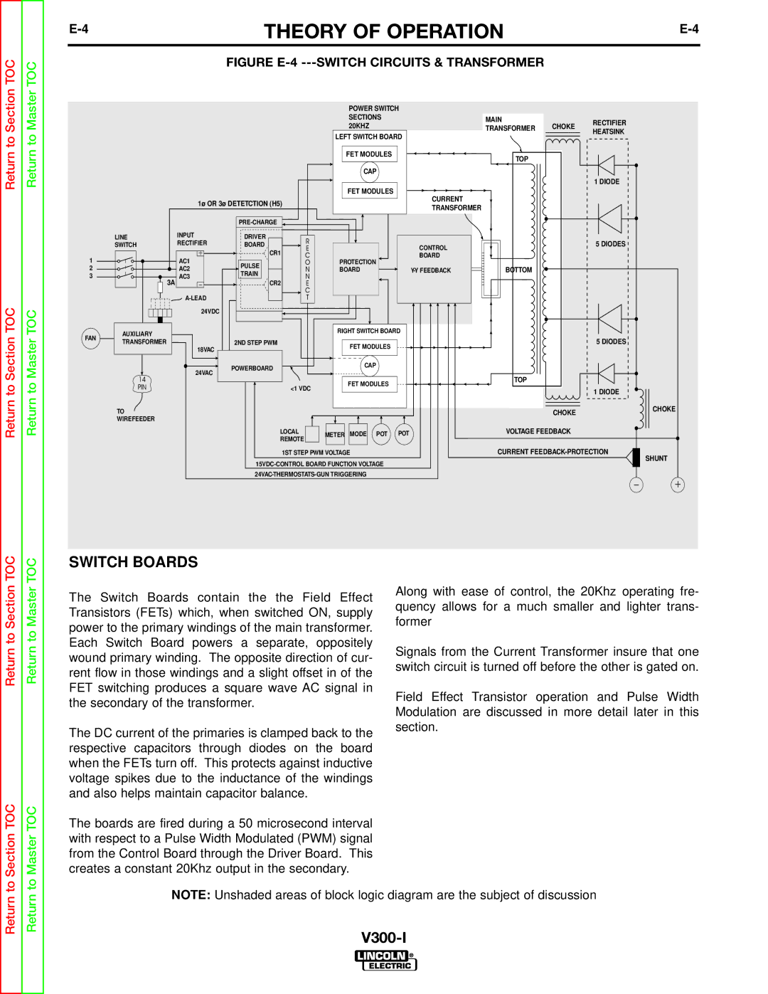
The Switch Boards contain the the Field Effect Transistors (FETs) which, when switched ON, supply power to the primary windings of the main transformer. Each Switch Board powers a separate, oppositely wound primary winding. The opposite direction of cur- rent flow in those windings and a slight offset in of the FET switching produces a square wave AC signal in the secondary of the transformer.
The DC current of the primaries is clamped back to the respective capacitors through diodes on the board when the FETs turn off. This protects against inductive voltage spikes due to the inductance of the windings and also helps maintain capacitor balance.
The boards are fired during a 50 microsecond interval with respect to a Pulse Width Modulated (PWM) signal from the Control Board through the Driver Board. This creates a constant 20Khz output in the secondary.
Along with ease of control, the 20Khz operating fre- quency allows for a much smaller and lighter trans- former
Signals from the Current Transformer insure that one switch circuit is turned off before the other is gated on.
Field Effect Transistor operation and Pulse Width Modulation are discussed in more detail later in this section.
Return
Return
NOTE: Unshaded areas of block logic diagram are the subject of discussion