Return to Section TOC
Return to Section TOC
Return to Section TOC
Return to Section TOC
Return to Master TOC
Return to Master TOC
Return to Master TOC
Return to Master TOC
TROUBLESHOOTING & REPAIR |
CAPACITOR REMOVAL AND REPLACEMENT (cont.)
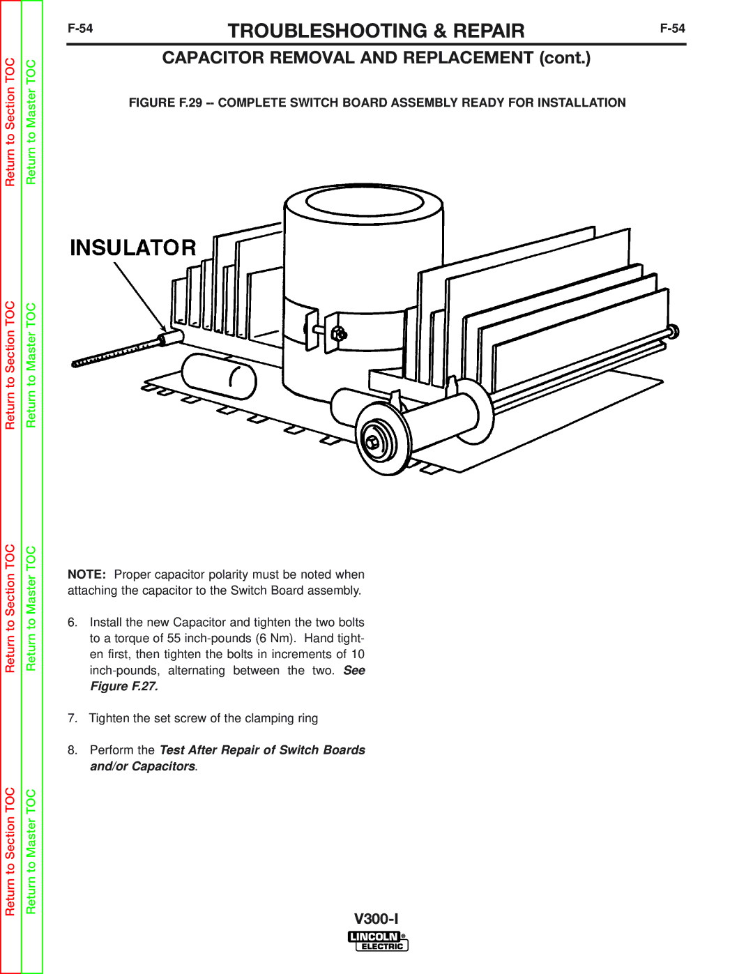
FIGURE F.29 -- COMPLETE SWITCH BOARD ASSEMBLY READY FOR INSTALLATION
NOTE: Proper capacitor polarity must be noted when attaching the capacitor to the Switch Board assembly.
6.Install the new Capacitor and tighten the two bolts to a torque of 55
Figure F.27.
7.Tighten the set screw of the clamping ring
8.Perform the Test After Repair of Switch Boards and/or Capacitors.