Return to Section TOC
Return to Section TOC
Return to Master TOC
Return to Master TOC
TROUBLESHOOTING & REPAIR |
OVERVOLTAGE PROTECTION DC TRIGGER CIRCUIT TEST (cont.)
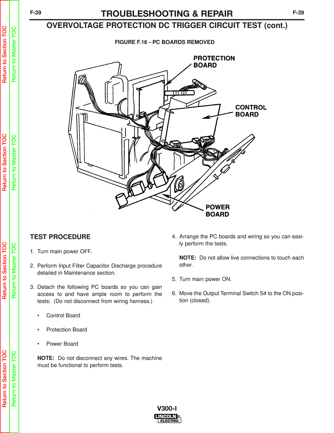
FIGURE F.16 - PC BOARDS REMOVED
Return to Section TOC
Return to Section TOC
Return to Master TOC
Return to Master TOC
TEST PROCEDURE
1.Turn main power OFF.
2.Perform Input Filter Capacitor Discharge procedure detailed in Maintenance section.
3.Detach the following PC boards so you can gain access to and have ample room to perform the tests: (Do not disconnect from wiring harness.)
•Control Board
•Protection Board
•Power Board
NOTE: Do not disconnect any wires. The machine must be functional to perform tests.
4.Arrange the PC boards and wiring so you can easi- ly perform the tests.
NOTE: Do not allow live connections to touch each other.
5.Turn main power ON.
6.Move the Output Terminal Switch S4 to the ON posi- tion (closed).