TROUBLESHOOTING & REPAIR | ||
|
|
|
TOC | TOC | OVERVOLTAGE PROTECTION DC TRIGGER CIRCUIT TEST (cont.) | |||||
|
|
|
|
|
| ||
Section | Master |
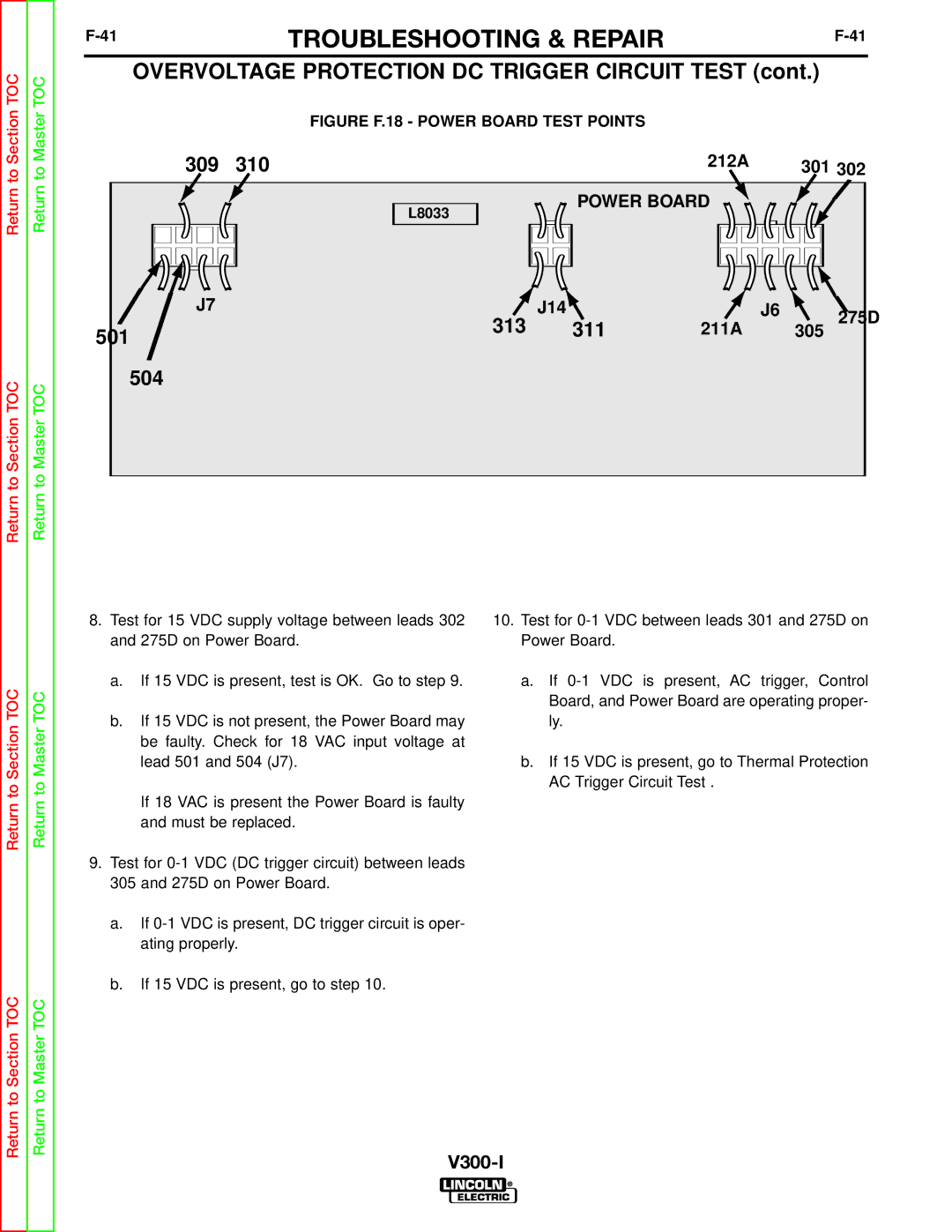
| FIGURE F.18 - POWER BOARD TEST POINTS |
|
|
| |
309 | 310 |
| 212A |
| 301 302 | ||
to | to |
|
| ||||
|
|
|
|
|
| ||
Return | Return |
| L8033 | POWER BOARD |
|
| |
|
|
|
|
| |||
|
|
|
|
|
| ||
|
| J7 | 313 | J14 |
| J6 | 275D |
|
|
| 311 | 211A |
| ||
|
| 501 |
| 305 | |||
|
|
|
|
|
|
| |
Return to Section TOC | Return to Master TOC | 504 |
|
|
|
|
|
|
|
|
|
|
| ||
|
| 8. Test for 15 VDC supply voltage between leads 302 | 10. Test for | |
|
| and 275D on Power Board. | Power Board. | |
TOC | TOC | a. | If 15 VDC is present, test is OK. Go to step 9. | a. If |
|
| Board, and Power Board are operating proper- | ||
|
|
|
| |
Section | Master | b. | If 15 VDC is not present, the Power Board may | ly. |
| be faulty. Check for 18 VAC input voltage at |
| ||
|
|
|
| |
|
|
| lead 501 and 504 (J7). | b. If 15 VDC is present, go to Thermal Protection |
to | to |
|
| AC Trigger Circuit Test . |
| If 18 VAC is present the Power Board is faulty |
| ||
Return | Return |
|
| |
| and must be replaced. |
| ||
|
|
|
| |
9.Test for
a.If
b.If 15 VDC is present, go to step 10.
Return to Section TOC | Return to Master TOC |
|