INSTALLATION |
Return to Section TOC
Return to Section TOC
Return to Section TOC
Return to Section TOC
Return to Master TOC
Return to Master TOC
Return to Master TOC
Return to Master TOC
POWER INPUT CONNECTION
Connect terminal marked ![]() to earth ground per any existing local or national electrical codes.
to earth ground per any existing local or national electrical codes.
Single Phase Input
Connect the supply lines to the upper and lower termi- nals of the line switch. Torque to 3.0 Nm. Do not use center terminal of the line switch.
Three Phase Input
Connect the supply lines to the line switch. Torque to 3.0 Nm.
Install in accordance with all local and national electric codes.
The
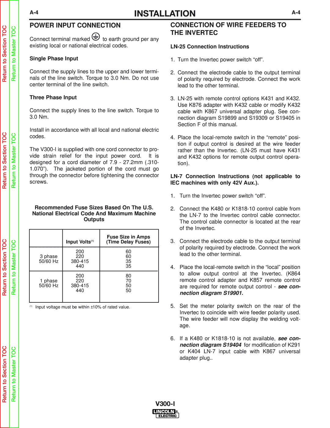
Recommended Fuse Sizes Based On The U.S.
National Electrical Code And Maximum Machine
Outputs
|
| Fuse Size in Amps | |
| Input Volts(1) | (Time Delay Fuses) | |
|
|
|
|
| 200 | 60 |
|
3 phase | 220 | 60 |
|
50/60 Hz | 35 |
| |
| 440 | 35 |
|
|
|
|
|
| 200 | 80 |
|
1 phase | 220 | 70 |
|
50/60 Hz | 50 |
| |
| 440 | 50 |
|
|
|
|
|
(1)Input voltage must be within ±10% of rated value.
CONNECTION OF WIRE FEEDERS TO THE INVERTEC
LN-25 Connection Instructions
1.Turn the Invertec power switch “off”.
2.Connect the electrode cable to the output terminal of polarity required by electrode. Connect the work lead to the other terminal.
3.
4.Place the
1.Turn the Invertec power switch “off”.
2.Connect the K480 or
3.Connect the electrode cable to the output terminal of polarity required by electrode. Connect the work lead to the other terminal.
4.Place the
5.Set the meter polarity switch on the rear of the Invertec to coincide with wire feeder polarity used. The wire feeder will now display the welding volt- age.
6.If a K480 or
