Chapter 4: Additional Information
Front of the Decoder
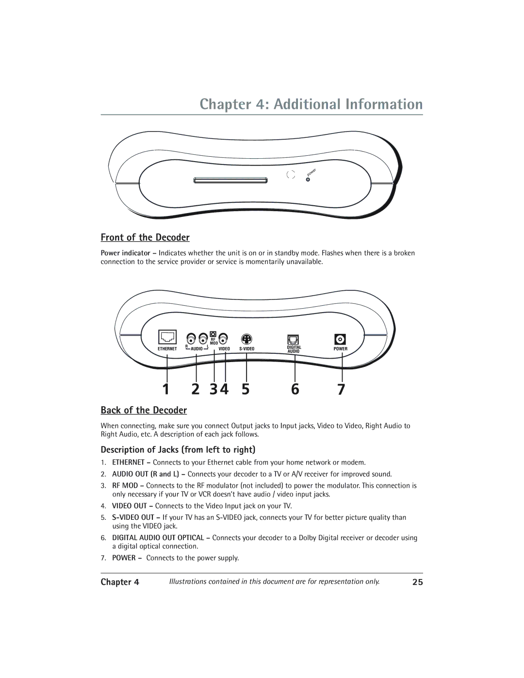
Power indicator – Indicates whether the unit is on or in standby mode. Flashes when there is a broken connection to the service provider or service is momentarily unavailable.
|
|
|
| RF |
|
|
| |
| R |
| L | MOD |
| DIGITAL |
| |
ETHERNET | AUDIO | VIDEO | POWER | |||||
|
| AUDIO | ||||||
|
|
|
|
|
|
|
1 | 2 | 3 4 | 5 | 6 | 7 |
Back of the Decoder
When connecting, make sure you connect Output jacks to Input jacks, Video to Video, Right Audio to Right Audio, etc. A description of each jack follows.
Description of Jacks (from left to right)
1.ETHERNET – Connects to your Ethernet cable from your home network or modem.
2.AUDIO OUT (R and L) – Connects your decoder to a TV or A/V receiver for improved sound.
3.RF MOD – Connects to the RF modulator (not included) to power the modulator. This connection is only necessary if your TV or VCR doesnÕt have audio / video input jacks.
4.VIDEO OUT – Connects to the Video Input jack on your TV.
5.
6.DIGITAL AUDIO OUT OPTICAL – Connects your decoder to a Dolby Digital receiver or decoder using a digital optical connection.
7.POWER – Connects to the power supply.
Chapter 4 | Illustrations contained in this document are for representation only. | 25 |
