Chapter 1: Connections & Setup
V T
TV
VIDEO |
| AUDIO | |
R | L / MONO | ||
| |||
|
| IN | |
|
| L |
OUT
CABLE/
ANTENNA
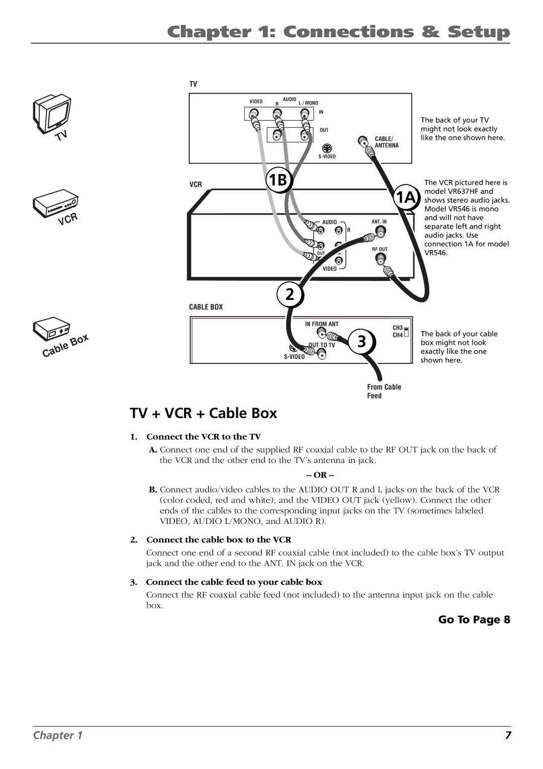
The back of your TV might not look exactly like the one shown here.
| R |
C | |
V |
|
VCR | 1B |
| The VCR pictured here is |
|
| 1A | model VR637HF and |
|
| shows stereo audio jacks. | |
|
|
| Model VR546 is mono |
| AUDIO | ANT. IN | and will not have |
| separate left and right | ||
| R |
| |
|
| audio jacks. Use | |
|
|
| |
| L | RF OUT | connection 1A for model |
| OUT IN | VR546. | |
|
| ||
| VIDEO |
|
|
|
|
|
|
| x |
|
|
|
| o | |
|
|
| B |
| |
|
| e |
|
| |
|
| l |
|
|
|
| b |
|
|
| |
a |
|
|
|
| |
C |
|
|
|
|
|
2
CABLE BOX
IN FROM ANT |
| CH3 |
|
| |
| 3 | CH4 |
OUT TO TV |
|
From Cable
Feed
The back of your cable box might not look exactly like the one shown here.
TV + VCR + Cable Box
1.Connect the VCR to the TV
A.Connect one end of the supplied RF coaxial cable to the RF OUT jack on the back of the VCR and the other end to the TV’s antenna in jack.
–OR –
B.Connect audio/video cables to the AUDIO OUT R and L jacks on the back of the VCR (color coded, red and white), and the VIDEO OUT jack (yellow). Connect the other ends of the cables to the corresponding input jacks on the TV (sometimes labeled VIDEO, AUDIO L/MONO, and AUDIO R).
2.Connect the cable box to the VCR
Connect one end of a second RF coaxial cable (not included) to the cable box’s TV output jack and the other end to the ANT. IN jack on the VCR.
3.Connect the cable feed to your cable box
Connect the RF coaxial cable feed (not included) to the antenna input jack on the cable box.
Go To Page 8
Chapter 1 | 7 |
