Users Guide
Product Registration
Information
Contents
How to hook up a stereo amplifier/receiver?
Optional Hookups How to hook up two VCRs for copying tapes?
Choosing a Hookup
What type of Cable-TV system* do you have?
Antenna or Cable System
Without
Cable Box
Advanced hookup
AIBasic hookup
Box to Unscramble Only Pay Channels
Cable System WdhCable
Position Cable Box
Such as HBO, Showtime, Pay-Per-View, etc
Basic hookup
Position RCA DSS receiver
Back of Satellite Receiver
Back of TV
RCA DSS Satellite Receiver
Plug in power cords of VCR, TV, and receiver
Advanced hookup with basic receiver
Deluxe receiver
Option a hookup
Connecting Two VCRs for Copying Tapes
Front View for front Audio/video input connection
Option B hookup
Amplifier/receiver Back of VCR
Connecting a Stereo Amplifier/Receiver
Receive a stereo broadcast Through an amplifier/receiver
Back Amplifier/Receiver
Startup
Check accessories with VCR
Insert batteries in remote
Turn on the VCR
Place channels in the VCRs memory
Add or remove channels from the VCRs memory
Use TVoVCR button
Set Auto TV/VCR feature
Skip this step it you used one of the advanced hookups
CH3 or CH4
Select the display panel brightness
Set the Automatic Daylight-Saving Time
Set the time and date
Press Menuprog on the remote to see
Component Buttons
VCR Function Buttons
DSSoCABLE
JOG Shuttle and %
TV Function Buttons
Cable Box or RCA DSS Receiver Function Buttons
VCR Function Buttons
Controlling a VCR
Program the VCR for Remote Control
Program the Remote for a TV
Controlling a TV
Operate the TV
Code
Controlling a Cable Box or an RCA DSS Receiver
Program the remote
Operate the Cable Box or Satellite Receiver
Operate the Auxiliary Component
Controlling an Auxiliary RCA Component
Program the Remote for an Auxiliary Component
AM/FM CD I Tape Phono RCA0307 t
To Play a Tape
Operating Instructions
Using the Playback Features
Tape Playback HI.FI/MIX/LINEAR Feature
To Select Playback Sound
Auto Play Feature
Auto Repeat Feature
Time Counter
Display Button
Slow Motion
Pause for Stop Action
Picture Search
Automatic Tracking
Variable Speed Picture Search Using Shuttle Ring on the VCR
Commercial Scan Search Button
Index Search
Index Search menu
Blank Search
Zero Search
Basic Recording- Operating Instructions
Types of Recordings
To Stop a Recording
To Make a Recording
Automatic Head Cleaner
Recording Features
Recording Speeds
Recording Pause
Operating Instructions
Express Recording
Display showing 30 minutes remaining
Stopping an Express Recording in Progress
To Record Stereo Broadcast TV or SAP
Recording Broadcast Stereo TV or SAP Second Audio Program
R jacks on the back of the VCR
Recording Audio Only
Manual Controlled Cable box or Satellite Receiver Press
Recording While Youre Away
Box Cable Systems, or Cable Box VCR Can Control
Recording While Youre Away VCR Plus+* Recording
Standardized VCR Plus+ Channel Numbers for Cable-TV
Canadian List
Stopping a Timer Recording in Progress
Setting a VCR Plus+ Recording
Recording While Youre Away VCR Plus+ Recording
Unrecognized NUMBER... Please RE-ENTER appears
Recording While Youre Away Timer Recording
Setting a Timer Recording
Stopping a Recording in Progress
Checking or Clearing VCR Plus+ or Timer Recordings
Timer Recording From the VCRs Line Input
Recording
SSuper-VHS Recording
Hookups
Operating Instructions Refer to hookup on
Using Two VCRs for Copying and Editing Tapes
To Audio Dub Refer to hookup on
Audio and Video Dubbing
To Video Dub Refer to hookup on page 8, Option B
To Audio and Video Dub
Front Panel
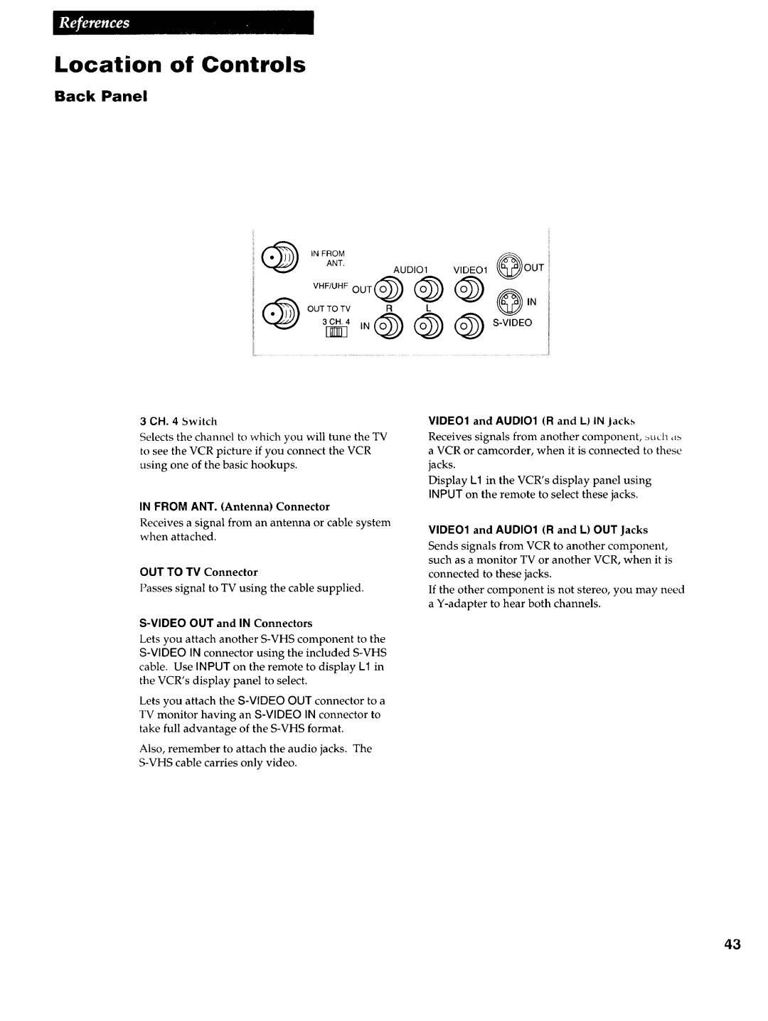
Location of Controls
Remote Sensor
Shuttle Ring
From ANT. Antenna Connector
CH Switch
Back Panel
VIDE01 and AUDIO1 R and L in jacks
Repeat VCR Indicator
Hi-Fi Indicator
Display Panel
Specifications
Cleaning the VCR
Tuner
Trouble Heres what Try
Trouble Checks
Tape
Cassette
Heres what to try
Trouble
Trouble Heres What To try
Limited Warranty
Index
I4-15,24
15,18,33
LISq Menu VCR PLUS+ Menu
Page
Part Number 95-VR725HF-1
Qo 11IOMSON Consumer Electronics