Gas Fireplaces
P36 - P36D Gas Fireplace
Framing and Finishing
1)Determine the total thickness of facing material (e.g. drywall plus ceramic tiles) to allow the fi nished surface to be fl ush with the front of the unit. Total facing thickness can vary from 1/2” (13mm) to
2)Frame in the enclosure for the unit with framing material.
Note: Header for the P36 must be installed vertically to maintain clearances to combustible materials. Non combustible header may be installed horizontally.
3)For exterior walls, insulate the enclosure to the same degree as the rest of the house, apply vapor barrier and drywall, as per local installation codes. (Do not insulate the fireplace itself.)
4)The top of the unit must not be closer than 32” (813mm) to the ceiling.
5)Combustible material may be brought up to the top and sides of the unit and be covered with ceramic tiles, bricks, rock or other suitable combustible fi nishing materials.
If using the Barcelona Surround, Kensington, Balmoral, or Tripoli Screen Door please note that framing and facing must be non combustible (12” on top and 6” on both sides) and that the Barcelona is only approved for installation with a single sidewall.
Note: The unit does not have to be completely enclosed in a chase. The clearance on top of the unit is 0” to the standoffs so combustible building materials can be laid directly on top of the standoffs. You must maintain proper clearances from the vent to combustible materials (See Below).
6)Use metal studs for framing where the minimum clearance from the vent to combustible material cannot be maintained.
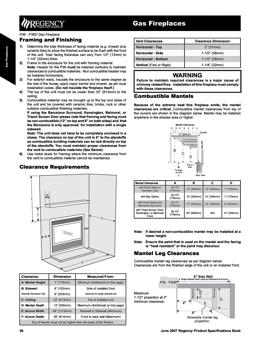
Clearance Requirements
D
B ![]()
Gas Fireplaces
Vent Clearances | Clearance Dimension |
Horizontal - Top | 2” (51mm) |
Horizontal - Side | |
Horizontal - Bottom | |
Vertical (Flex or Rigid) |
WARNING
Failure to maintain required clearances is a major cause of chimney related fires. Installation of this fireplace must comply with these clearances.
Combustible Mantels
Because of the extreme heat this fireplace emits, the mantel clearances are critical. Combustible mantel clearances from top of the louvers are shown in the diagram below. Mantel may be installed anywhere in the shaded area or higher.
Mantel Clearances
12 | 10 | 8 | 6 | 4 | 2 | 0 |
|
|
| 12" (305mm) |
|
| Drywall | ||
|
|
|
|
| |||
|
|
| Standoff | ||||
|
|
| |||||
| B |
|
|
|
|
| |
|
| C |
|
|
|
| |
|
|
| D |
|
|
| |
|
|
|
|
|
|
| |
0 |
|
|
|
|
|
|
|
|
| A |
| Top of |
|
| |
|
|
| Unit |
|
|
| |
To base
of Unit
Side View
Mantel Clearances | A | B | C | D | |
with Flush Glass or | 14” (356mm) | 10” (254mm) | 7” (178mm) | ||
Hampton Cast | (778mm) | ||||
|
|
| |||
with Bay Option | 13” (330mm) | 10” (254mm) | 7” (178mm) | ||
(778mm) | |||||
|
|
|
| ||
with Flush Glass and | 17” (432mm) | 12” (305mm) | 8” (203mm) | ||
Barcelona Surround | (778mm) | ||||
|
|
| |||
with Tripoli Screen Door, |
|
|
| ||
Kensington, or Balmoral | 20” (508mm) | N/A | 12” (305mm) | ||
(778mm) | |||||
Front |
|
|
| ||
|
|
|
|
Note: If desired a
Note: Ensure the paint that is used on the mantel and the facing is “heat resistant” or the paint may discolour.
Mantel Leg Clearances
Combustible mantel leg clearances as per diagram below: Clearances are from the fi nished edge of the unit or an installed front.
Clearance: | Dimension | Measured From: |
A: Mantel Height | 7” (178mm) | Minimum (Additional on this page) |
B: Sidewall | 6” (152mm) | Side of installed front |
Sidewall: Barcelona Only | 8” (203mm) | Approved for single sidewall only |
C: Ceiling | 32” (813mm) | Top of installed unit |
D: Mantel Depth | 12” (305mm) | Maximum (Additional on this page) |
E: Alcove Width | 48” (1219mm) | Sidewall to Sidewall (Minimum) |
F: Alcove Depth | 36” (914mm) | Front to back wall (Maximum) |
|
|
|
Top of Hearth must not be higher than the base of the fi rebox.
P36 - P36D
Maximum
6" Side Wall
8" Single Sidewall when using the Barcelona Surrround
Mantelleg | Mantelleg | 3" | |
2" |
|
|
|
5" |
|
|
|
Allowable mantel leg |
| ||
projection. |
|
| |
36
June 2007 Regency Product Specifications Book