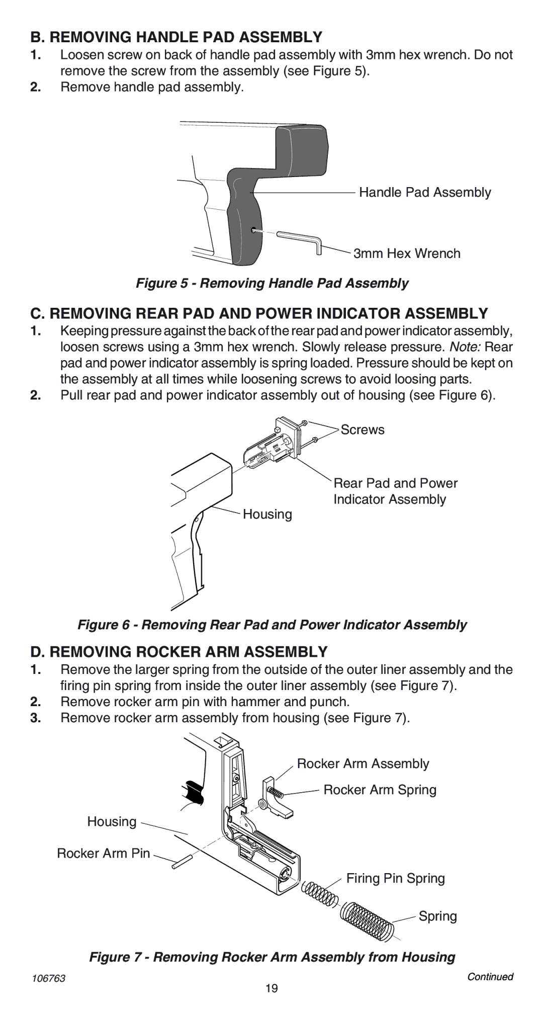
B. REMOVING HANDLE PAD ASSEMBLY
1.Loosen screw on back of handle pad assembly with 3mm hex wrench. Do not remove the screw from the assembly (see Figure 5).
2.Remove handle pad assembly.
Handle Pad Assembly
![]() 3mm Hex Wrench
3mm Hex Wrench
Figure 5 - Removing Handle Pad Assembly
C. REMOVING REAR PAD AND POWER INDICATOR ASSEMBLY
1.Keeping pressure against the back of the rear pad and power indicator assembly, loosen screws using a 3mm hex wrench. Slowly release pressure. Note: Rear pad and power indicator assembly is spring loaded. Pressure should be kept on the assembly at all times while loosening screws to avoid loosing parts.
2.Pull rear pad and power indicator assembly out of housing (see Figure 6).
![]()
![]()
![]() Screws
Screws
Rear Pad and Power
Indicator Assembly
![]() Housing
Housing
Figure 6 - Removing Rear Pad and Power Indicator Assembly
D. REMOVING ROCKER ARM ASSEMBLY
1.Remove the larger spring from the outside of the outer liner assembly and the firing pin spring from inside the outer liner assembly (see Figure 7).
2.Remove rocker arm pin with hammer and punch.
3.Remove rocker arm assembly from housing (see Figure 7).
Rocker Arm Assembly
Rocker Arm Spring
Housing
Rocker Arm Pin
Firing Pin Spring
Spring
Figure 7 - Removing Rocker Arm Assembly from Housing
106763 | Continued |
19