ASSEMBLY
A-FRAME ATTACHMENT (cont'd.)
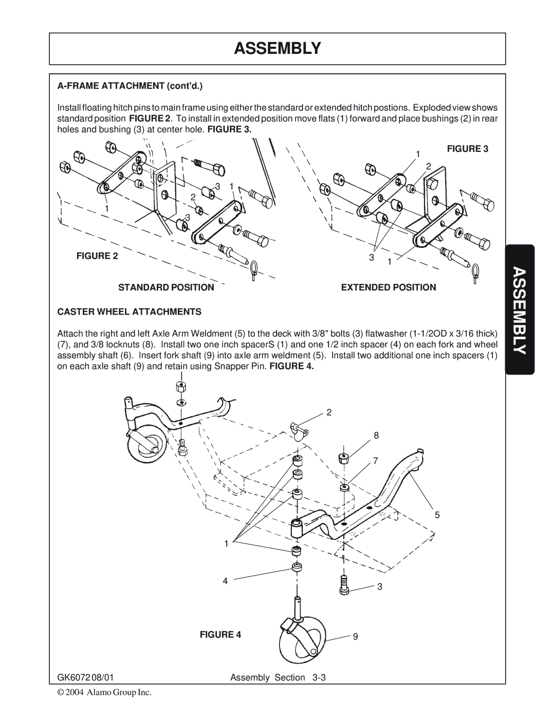
Install floating hitch pins to main frame using either the standard or extended hitch postions. Exploded view shows standard position FIGURE 2. To install in extended position move flats (1) forward and place bushings (2) in rear holes and bushing (3) at center hole. FIGURE 3.
1 | FIGURE 3 |
| |
| 2 |
3 | 1 |
|
2 |
|
|
1 |
|
|
3 |
|
|
FIGURE 2 | 3 | 1 |
|
| |
STANDARD POSITION | EXTENDED POSITION | |
CASTER WHEEL ATTACHMENTS
Attach the right and left Axle Arm Weldment (5) to the deck with 3/8" bolts (3) flatwasher
2
8
7
5
1 |
|
4 | 3 |
|
| FIGURE 4 | 9 |
GK6072 08/01 | Assembly Section | |
© 2004 Alamo Group Inc. |
|
|