258/258XL Power Pipe Cutters
![]() WARNING To avoid electrical shock and electrical fires, never use an extension cord that is damaged or does not meet the following requirements:
WARNING To avoid electrical shock and electrical fires, never use an extension cord that is damaged or does not meet the following requirements:
•The cord has a
•The cord is rated as “W” or
•The cord has sufficient wire thickness (14 AWG below 25′/12 AWG 25′ - 50′). If the wire thickness is too small, the cord may overheat, melting the cord’s insulation or causing nearby objects to ignite.
![]() WARNING To reduce risk of electrical shock, keep all electrical connections dry and off the ground. Do not touch plug with wet hands.
WARNING To reduce risk of electrical shock, keep all electrical connections dry and off the ground. Do not touch plug with wet hands.
6.Check the Power Drive to insure it is operating properly.
•Depress the switch and make sure it controls the stopping of the Power Drive by releasing the switch.
•Depress and hold the switch. Inspect the moving parts for misalignment, binding, odd noises or any other unusual conditions that may affect the safe and normal operation of the tool. If such condi- tions are present, have the power drive serviced.
•Depress switch in the opposite direction. Check that the power drive rotates in an opposite direction.
Using Pipe Supports
CAUTION
Pipe supports must be used to prevent cutter wheel damage. Failure to properly support the pipe will result in shortened wheel life.
Two (2) ball transfer head pipe supports are shipped with the 258 and 258XL Cutters. When cut- ting pipe in lengths of 18″ or longer, additional pipe supports must be used.
1.As shown in Figure 6, the cutter and pipe supports must be positioned so that the pipe sections have a tendency to fall away from the cutter blade as the pipe is cut. If the cutter wheel is pinched by the pipe, it will damage the cutter wheel.
INCORRECT
CORRECT
Figure 6 – Position Pipe Supports So That Cutter Wheel Is Not Pinched By The Pipe
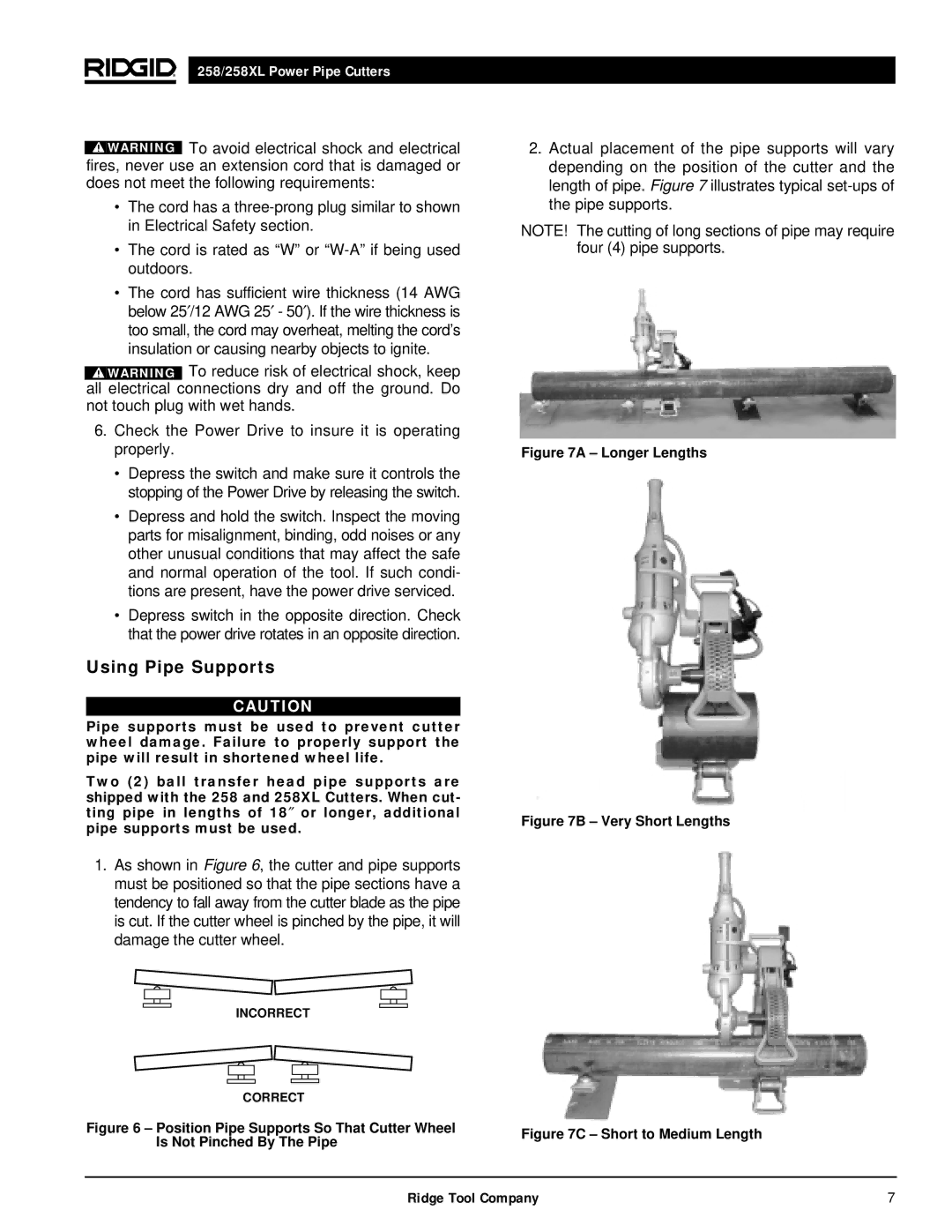
2.Actual placement of the pipe supports will vary depending on the position of the cutter and the length of pipe. Figure 7 illustrates typical
NOTE! The cutting of long sections of pipe may require four (4) pipe supports.
Figure 7A – Longer Lengths
Figure 7B – Very Short Lengths
Figure 7C – Short to Medium Length
Ridge Tool Company | 7 |