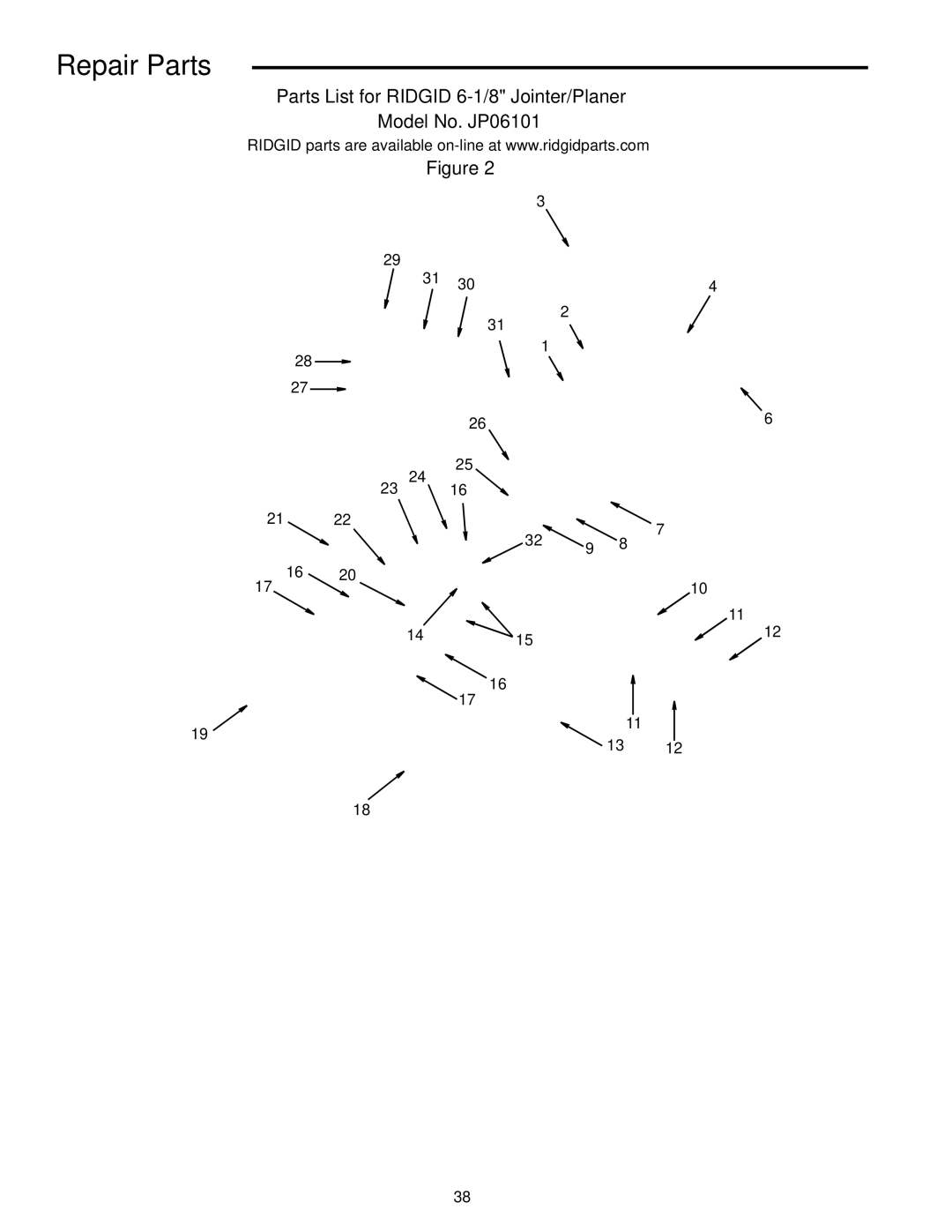
Manuals
/
RIDGID
/
Power Tools
/
Planer
RIDGID
JP0610 manual Repair Parts
Models:
JP0610
1
38
44
44
Download
44 pages
56.12 Kb
35
36
37
38
39
40
41
42
<
>
Troubleshooting
Install
Repair Parts
Wiring Diagram
Wire Sizes
Assembly
Adjusting Table Extension
On-Off Switch
Page 38
Image 38
Page 37
Page 39
Page 38
Image 38
Page 37
Page 39
Contents
235$725·60$18$
Table of Contents
Safety Instructions For Jointer/Planer
Before Using the Jointer/Planer
Major Hazards
Safety Labels and Indicators on the Jointer/Planer
Plan Ahead To Protect Your Eyes, Hands, Face and Ears
Inspect Your Workpiece
Keep Children Away
Whenever Jointer/Planer Is Running
Before Leaving the Jointer/Planer
Don’t Force Tool
Glossary of Terms for Woodworking
Motor Specifications and Electrical Requirements
Power Supply and Motor Specifications
Changing Motor Voltage
General Electrical Connections
Volt, 60 Hz. Tool Information
Prong Plug Properly Grounded Outlet Grounding
Extension Gauge A.W.G Cord Length
Motor Safety Protection
Wire Sizes
Unpacking and Checking Contents
Loose Parts
Loose Parts From Hardware Pack
Serrated Hex Bolt
Assembly
Cabinet and Motor Mount Assembly
Mounting the Motor
Install the Leveling Feet
Serrated Flange Hex Nut 5/16 Motor Assembly With Switch
Carriage Head Bolt 16-18 x 1/2
Align Belt Tighten Motor Mount Nuts
Tensioning Belt and Installing Rear Panel
Mounting Jointer Table to Cabinet
Serr 3/16-24 x 3/8 Belt Guard
Installing the Pulley Guard
Installing Handwheel
20 x 5/8
Tool Storage Sawdust Chute Screw Wing 1/4-20 x 5/8
Adjusting Table Extension
Attach Sawdust Chute
Outfeed Socket Head Screw Extension even with Outfeed table
Assemble Fence To Bed
Install Cutter Head Guard
Assembly Fence Nut Mount
Fence Lock Knob Nut Washer 1/2 Actual Size Not
Cutter Head Guard Functional Check
Adjusting Guard Spring
Adjusting the Leveling Feet
Pan Head Screw Knob
Page
On-Off Switch
Angle Gauge
Cutter Knife Alignment/Adjustments
Alignments
Cutter Knife Sharpening
11/16 Wide New Blade Second Cutting Ground Surface Edge
Outfeed Table Adjustment
Angle Gauge Use
Adjusting Table Gibs
Fence Tilt Use and Bevel Stop Adjustment
Stop Screw Bar
Fence Slide Lock Knob Bevel Lock Handle
Safety Instructions for Basic Jointer/Planer Operation
Before Each Use
Push blocks and push sticks
Always Use Push Blocks When Planing, Beveling Or Chamfering
Feeding the Workpiece All Operations
Plan your work
Inspect your workpiece
Before Leaving the jointer/planer
Stop Pin Operation
Basic Jointer/Planer Cutting Operations
Depth of Cut Handwheel Operation
Feeding the Workpiece
Beveling/Chamfering
Planing
Jointing
Jointing Without Push Blocks
Support Long Workpieces
Using the Hold-Down/Push-Blocks
Rabbeting
Face Rabbet End Edge
Sliding Fence Operation
Sliding Lock Knob
Maintenance
Maintenance and Lubrication
Wiring Diagram
Lubrication
Trouble Probable Cause Remedy
Troubleshooting Guide
General
Motor
Repair Parts
2120 45 46
Always order by Part Number Not by Key Number Description
Key Description
Repair Parts
Repair Parts
Repair Parts
Key Description 118615 Nut Hex 3/8-16
Key Description
Repair Parts
DAY Satisfaction Guarantee Policy
Call