Model
6.If current is below 15 amps on
7.Continue until 15 amps is reached but not exceeded; D switch setting is used with long runs.
Multi-Zone System
If you are dealing with
1.Make sure unit is unplugged and switch is in the OFF position and cables are completely uncoiled.
2.Place the pipe clamps several feet apart.
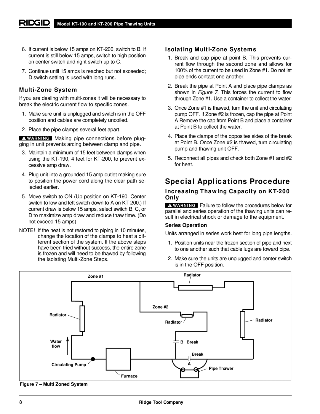
Isolating Multi-Zone Systems
1.Break and cap pipe at point B. This prevents cur- rent flow through the second zone and allows for 100% of the current to be used in Zone #1. Do not let pipe ends contact one another.
2.Break the pipe at Point A and place pipe clamps as shown in Figure 7. This forces the current to flow through Zone #1. Use a container to collect the water.
3.Once Zone #1 is thawed, turn the unit and circulating pump OFF. If Zone #2 is frozen, cap the pipe at Point A Remove the cap from Point B and place a container at Point B to collect the water.
![]() WARNING Making pipe connections before plug- ging in unit prevents arcing between clamp and pipe.
WARNING Making pipe connections before plug- ging in unit prevents arcing between clamp and pipe.
3.Maintain a minimum of 15 feet between clamps when using the
4.Plug unit into a grounded 15 amp outlet making sure to position the power cord along the clear path se- lected earlier.
5.Move switch to ON (Up position on
NOTE! If the heat is not restored to piping in 10 minutes, change the location of the clamps to heat a dif- ferent section of the system. If the above steps have been tried without success, the entire zone is frozen and will need to be thawed by following the Isolating
4.Place the clamps of the opposites sides of the break at Point B. Once Zone #2 is thawed, turn circulating pump and thawing unit OFF.
5.Reconnect all pipes and check both Zone #1 and #2 for heat.
Special Applications Procedure
Increasing Thawing Capacity on KT-200 Only
![]() WARNING Failure to follow the procedures below for parallel and series operation of the thawing units can re- sult in electrical shock or damage to the equipment.
WARNING Failure to follow the procedures below for parallel and series operation of the thawing units can re- sult in electrical shock or damage to the equipment.
Series Operation
Units arranged in series work best for long pipe lengths.
1.Position units near the frozen section of pipe and next to one another such that cable lugs are toward pipe.
2.Make sure the units are unplugged and center switch is in the OFF position.
Zone #1 | Radiator |
|
| Zone #2 |
Radiator |
|
| Radiator |
Water | B Break |
flow |
|
| Break |
Circulating Pump | A |
| Furnace |
Radiator
Pipe Thawer
Figure 7 – Multi Zoned System
8 | Ridge Tool Company |