Model
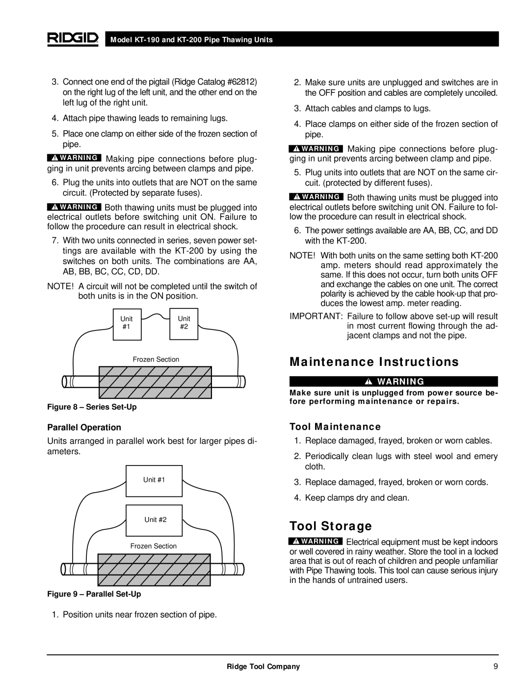
3.Connect one end of the pigtail (Ridge Catalog #62812) on the right lug of the left unit, and the other end on the left lug of the right unit.
4.Attach pipe thawing leads to remaining lugs.
5.Place one clamp on either side of the frozen section of pipe.
![]() WARNING Making pipe connections before plug- ging in unit prevents arcing between clamps and pipe.
WARNING Making pipe connections before plug- ging in unit prevents arcing between clamps and pipe.
6.Plug the units into outlets that are NOT on the same circuit. (Protected by separate fuses).
![]() WARNING Both thawing units must be plugged into electrical outlets before switching unit ON. Failure to follow the procedure can result in electrical shock.
WARNING Both thawing units must be plugged into electrical outlets before switching unit ON. Failure to follow the procedure can result in electrical shock.
7.With two units connected in series, seven power set- tings are available with the
NOTE! A circuit will not be completed until the switch of both units is in the ON position.
Unit | Unit |
#1 | #2 |
| Frozen Section |
|
|
|
|
Figure 8 – Series Set-Up
2.Make sure units are unplugged and switches are in the OFF position and cables are completely uncoiled.
3.Attach cables and clamps to lugs.
4.Place clamps on either side of the frozen section of pipe.
![]() WARNING Making pipe connections before plug- ging in unit prevents arcing between clamp and pipe.
WARNING Making pipe connections before plug- ging in unit prevents arcing between clamp and pipe.
5.Plug units into outlets that are NOT on the same cir- cuit. (protected by different fuses).
![]() WARNING Both thawing units must be plugged into electrical outlets before switching unit ON. Failure to fol- low the procedure can result in electrical shock.
WARNING Both thawing units must be plugged into electrical outlets before switching unit ON. Failure to fol- low the procedure can result in electrical shock.
6.The power settings available are AA, BB, CC, and DD with the
NOTE! With both units on the same setting both
IMPORTANT: Failure to follow above
Maintenance Instructions
![]() WARNING
WARNING
Make sure unit is unplugged from power source be- fore performing maintenance or repairs.
Parallel Operation
Units arranged in parallel work best for larger pipes di- ameters.
Unit #1
Unit #2
Frozen Section
Figure 9 – Parallel Set-Up
1. Position units near frozen section of pipe.
Tool Maintenance
1.Replace damaged, frayed, broken or worn cables.
2.Periodically clean lugs with steel wool and emery cloth.
3.Replace damaged, frayed, broken or worn cords.
4.Keep clamps dry and clean.
Tool Storage
![]() WARNING Electrical equipment must be kept indoors or well covered in rainy weather. Store the tool in a locked area that is out of reach of children and people unfamiliar with Pipe Thawing tools. This tool can cause serious injury in the hands of untrained users.
WARNING Electrical equipment must be kept indoors or well covered in rainy weather. Store the tool in a locked area that is out of reach of children and people unfamiliar with Pipe Thawing tools. This tool can cause serious injury in the hands of untrained users.
Ridge Tool Company | 9 |
